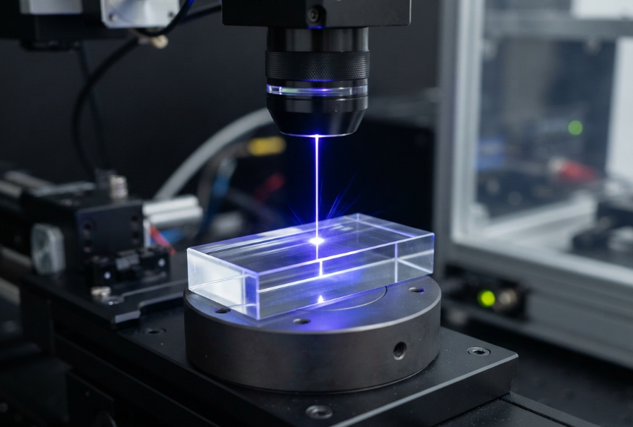
When brittle materials like cover glass, sapphire, or quartz fracture during laser cutting, the instinct is almost universally the same: dial back the power. Engineers meticulously reduce single-pulse energy, convinced that thermal damage is the root cause of the micro-cracks. But in the realm of ultrafast laser cutting, this intuition is fundamentally flawed. Ultrafast pulses operate on the principle of cold ablation; they remove material before heat can propagate. If you are still seeing edge cracks, heat isn’t your problem. The true culprit is the invisible shockwave generated by sub-micron plasma plumes, which embeds lateral tensile stress deep into the substrate.
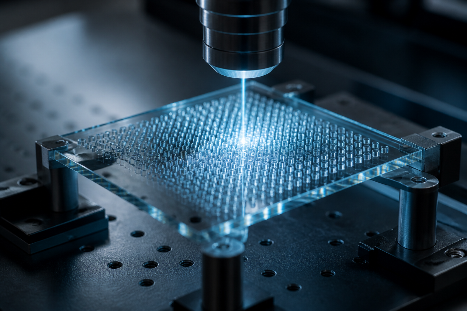
“Faced with edge micro-cracks on an aluminosilicate drilling line, the instinct was to drop single-pulse energy. The cracks persisted. The failure wasn’t thermal—ultrafast ‘cold ablation’ had already eliminated melt. The culprit was the sub-micron plasma plume’s shockwave, which embedded lateral tensile stress into the substrate. Shifting strategy from energy reduction to managing pulse overlap (dropping rep rate to 400 kHz at 8000 mm/s scan speed) and integrating a top-hat beam shaper to flatten the axial energy gradient, reduced delayed fracture in thermal cycling tests from 3% to under 200 ppm. Eliminating micro-cracks requires managing stress release paths, not just minimizing heat.”
— process engineer, aluminosilicate cover-glass drilling line qualification
This observation fundamentally changes how we approach brittle material processing. If you want to achieve high yields in ultrafast laser cutting of brittle materials, you must stop thinking about thermal management and start thinking about mechanical stress confinement.
To eliminate micro-cracks in ultrafast laser cutting of brittle materials, you must manage the plasma shockwave’s residual stress rather than simply reducing laser power. This is achieved by optimizing pulse overlap to prevent cumulative stress loading and employing beam shaping—like top-hat or Bessel beams—to flatten the axial energy gradient, allowing the material’s tensile threshold to remain unbreached.
If you are qualifying a laser system for brittle materials, you are likely caught in a frustrating loop. The cut looks perfect under the microscope immediately after processing, but parts fail during post-cut tempering, thermal cycling tests (TCT), or worse, shatter in the customer’s hands weeks later. This phenomenon, known as delayed fracture, is the nightmare of brittle material manufacturing.
In our experience across more than 50 projects involving sapphire wafer dicing, aluminosilicate glass drilling, and thick quartz cutting, we have seen the same scenario repeat. Engineers tweak pulse energy endlessly, only to watch yield rates stagnate. The problem is that standard parameter windows do not account for the mechanical stress fields induced by high-density plasmas.
When brittle materials fail, they don’t fail because they melted; they fail because the localized shockwave exceeded the material’s ultimate tensile strength (UTS), creating sub-surface micro-cracks that propagate over time. Recognizing that plasma shockwave residual stress is the root cause is the first step to actually solving the problem and achieving a truly zero-defect production line.
The foundation of eliminating micro-cracks is understanding the physics of ultrafast ablation. When a picosecond or femtosecond pulse strikes a transparent brittle material, the extreme intensity instantaneously ionizes the substrate, creating a high-pressure plasma plume. This rapid expansion generates a mechanical shockwave that propagates laterally into the material.
If the peak pressure of this shockwave exceeds the material’s tensile threshold, micro-fractures are embedded into the substrate[1]. Reducing the pulse energy doesn’t fix this; it merely scales down the plasma, often dropping the ablation efficiency below the threshold needed to remove material, leaving behind a different kind of defect. The solution is not to starve the process of energy, but to shape how that energy interacts with the material.
Common Mistake: Endlessly tuning pulse energy down to avoid cracks, resulting in a slow process that still suffers from delayed fracture because the fundamental shockwave pressure remains too high relative to the material’s UTS.
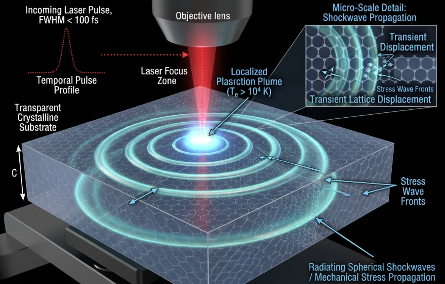
Once you understand that shockwaves are the issue, scanning strategy becomes critical. In ultrafast laser cutting, pulses are laid down in an overlapping train. If the pulse overlap is too high, the shockwave from the second pulse hits the stress field of the first pulse before it has time to dissipate. This cumulative stress loading rapidly multiplies the mechanical force on the substrate, guaranteeing micro-cracks.
To solve this, you must control the pulse duty cycle and overlap. As the process engineer in our opening hook discovered, dropping the repetition rate to 400 kHz while maintaining an 8000 mm/s scan speed [2] effectively spaces the pulses out enough to allow the plasma expansion to cool and the localized stress field to relax before the next pulse arrives. Preventing cumulative stress loading is often more effective than changing the laser source itself.
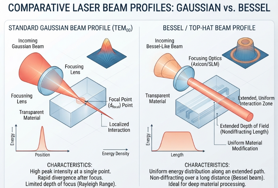
The most significant leap in eliminating micro-cracks comes from optical engineering. A standard Gaussian beam has a steep axial energy gradient—the energy is intensely concentrated at the focal point and drops off rapidly. This creates a highly localized, extremely high-pressure plasma that acts like a microscopic chisel, trapping shockwaves inside the kerf and maximizing stress concentration.
The solution is beam shaping. Integrating a top-hat beam shaper flattens the energy distribution across the focal spot[3], creating a uniform plasma field rather than a pinpoint explosion. This distributes the mechanical stress over a wider area, preventing the peak pressure from exceeding the material’s tensile threshold.
“When delayed micro-cracking appeared in sapphire wafer dicing, the development lead spec’d a femtosecond source—shorter pulse, less heat, defensibly fewer cracks. But bench tests showed the cracks weren’t driven by pulse duration; they were driven by the steep axial energy gradient of a Gaussian focus, which trapped plasma shockwaves inside the kerf. A 100W picosecond source equipped with a Bessel beam module extended the Rayleigh length by 3x, distributing the plasma field and allowing stress to dissipate uniformly. The femtosecond upgrade was abandoned, saving $120k in capex and holding edge fracture rates at near-zero during 100°C thermal shock validation. The spec sheet didn’t list axial stress distribution; but it determined the yield.”
— R&D lead, sapphire wafer dicing source selection
For applications requiring deep cuts or thick materials, a Bessel beam is even more effective. A Bessel beam creates an elongated, non-diffracting focus, extending the Rayleigh length by up to 3x. This distributes the plasma field deep into the material along the optical axis, allowing lateral stress to dissipate uniformly rather than accumulating at a single focal point.
| Feature | Gaussian Beam | Top-Hat / Bessel Beam |
|---|---|---|
| Energy Gradient | Steep, highly localized | Flat, uniformly distributed |
| Plasma Behavior | Pinpoint, extreme pressure | Distributed, even pressure |
| Stress Confinement | Trapped in kerf, high peak stress | Dissipates uniformly, low peak stress |
| Micro-Crack Risk | High | Near Zero |
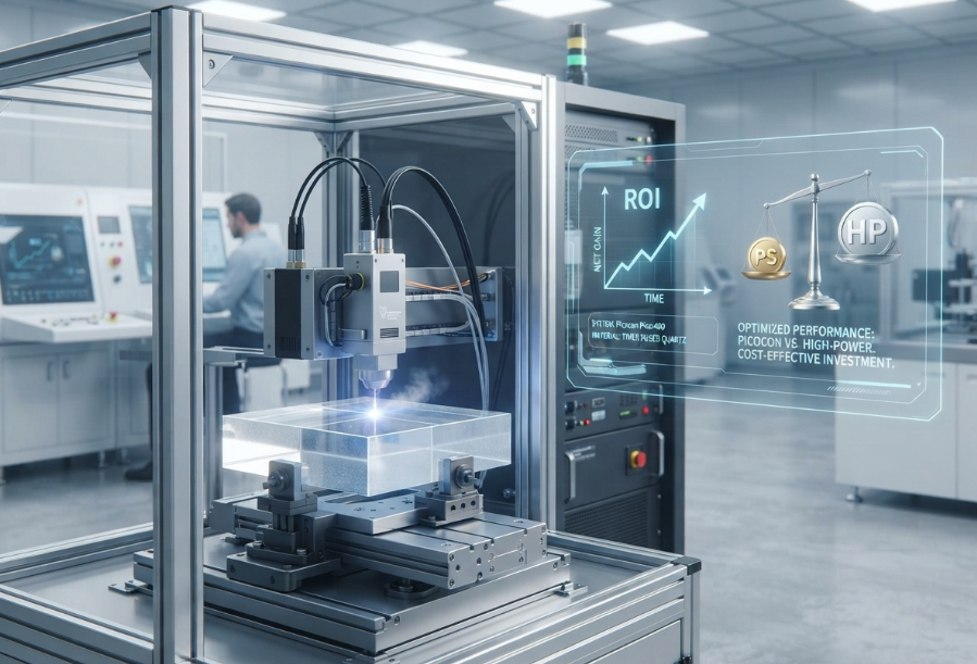
When sourcing equipment, there is a strong bias to future-proof the line by purchasing the highest peak power and shortest pulse duration available—often a 50W femtosecond setup. However, this over-specification directly amplifies the shockwave problem.
Ultra-high peak power generates extreme plasma densities. In thick quartz cutting, this extreme density creates localized stress fields that easily exceed the material’s tensile threshold. The solution is not a shorter pulse or more power. Transitioning to a 100W picosecond source allows for higher average power (for throughput) while strictly tuning the pulse duty cycle keeps the peak power manageable. Over-specifying peak power amplifies the very shockwave field that causes the cracks, turning a “premium” laser into a liability.
If you’re scaling up production, talking to a supplier directly can surface details about duty cycle tuning that no product listing will tell you.
To specify the right system for your brittle material cutting line, use this framework:
Eliminating micro-cracks in brittle materials requires balancing plasma physics, beam optics, and scanning dynamics. A laser’s spec sheet won’t tell you how its peak power will interact with your specific material’s tensile threshold. You need empirical data and optical engineering. If you’re sourcing at scale, talking to a supplier directly can surface details no product listing will tell you.
Talk to our sourcing team →
The instinct to treat micro-cracks as a thermal issue has cost manufacturers millions in failed yields and unnecessary femtosecond capex. In the world of ultrafast laser cutting of brittle materials, you don’t eliminate cracks by going easy on the material; you eliminate them by shaping the shockwave. Mastering the mechanical stress of plasma expansion, rather than just avoiding heat, is what separates a truly zero-defect brittle material line from a scrap-generating one.
Why do ultrafast lasers still cause micro-cracks in brittle materials if they are “cold ablation” processes?
While ultrafast lasers eliminate thermal damage (melt), they generate high-pressure plasma plumes during ablation. The mechanical shockwave from this plasma expansion embeds lateral tensile stress into the brittle substrate. If this shockwave exceeds the material’s tensile strength, sub-surface micro-cracks form, leading to delayed fracture.
Is a femtosecond laser better than a picosecond laser for preventing micro-cracks?
Not necessarily. If the beam profile is Gaussian, even a femtosecond laser will trap shockwaves and cause micro-cracks. A picosecond laser equipped with a Bessel beam module often performs better and is more cost-effective. It extends the Rayleigh length, distributing the plasma field and reducing peak stress, saving over $100k in capex compared to fs alternatives.
What is the best pulse overlap for cutting brittle materials without micro-cracks?
Pulse overlap should be kept under 40% to manage cumulative stress loading. This allows the plasma expansion from one pulse to cool and dissipate before the next pulse arrives, preventing the mechanical shockwaves from compounding and breaching the material’s ultimate tensile strength.
How does a Bessel beam prevent micro-cracks in sapphire wafer dicing?
A Bessel beam creates a non-diffracting, elongated focus that extends the Rayleigh length by up to 3x. This flattens the axial energy gradient, distributing the plasma field deep into the material along the optical axis. This allows lateral stress to dissipate uniformly, preventing the high peak pressures that cause localized micro-fractures.
What is delayed fracture in glass cutting?
Delayed fracture occurs when sub-surface micro-cracks, induced by the laser’s plasma shockwave, are not immediately visible but propagate over time. The part passes initial inspection but shatters during post-cut tempering, thermal cycling tests, or even in the customer’s hands due to residual tensile stress.
How does a top-hat beam shaper improve brittle material cutting?
A top-hat beam shaper converts a standard Gaussian beam into a flat energy distribution. Instead of a pinpoint of extreme energy, the focal spot applies uniform energy. This creates an even plasma field, distributing mechanical stress over a wider area and preventing the peak pressure from exceeding the material’s tensile threshold.
[1]”Evolution of the Laser-Induced Spallation Technique in Film … – PMC”. Studies of laser ablation and laser shock processing describe how shock-wave pressures that exceed a material’s dynamic tensile or spall strength can nucleate cracks or subsurface damage in brittle substrates. Evidence role: mechanism; source type: paper. Supports: Shock-wave pressure above a material’s tensile threshold can generate micro-fractures in the substrate.. Scope note: Support is strongest for specific material classes and laser regimes; the threshold and fracture morphology vary with pulse duration, wavelength, fluence, and substrate properties.→
[2]”Effect of Laser Pulse Overlap and Scanning Line Overlap on … – PMC”. Laser-processing studies describe pulse pitch as the scan speed divided by pulse repetition rate and show that pulse spacing/overlap influences heat accumulation, plasma shielding, and residual stress; here, 8000 mm/s at 400 kHz corresponds to an approximately 20 µm pulse spacing. Evidence role: mechanism; source type: paper. Supports: Reducing repetition rate to 400 kHz while scanning at 8000 mm/s increases pulse spacing enough to reduce cumulative plasma/thermal and stress effects.. Scope note: This supports the physical basis and pulse-spacing calculation, but it may not directly verify the specific process engineer’s observed outcome without material- and geometry-specific data.→
[3]”Gaussian-to-top-hat beam shaping: an overview of …”. Beam-shaping literature describes top-hat, or flat-top, laser profiles as redistributing optical intensity to produce a more uniform irradiance over the target area, supporting the stated optical mechanism. Evidence role: mechanism; source type: paper. Supports: A top-hat beam shaper flattens the energy distribution across the focal spot.. Scope note: This supports the beam-profile transformation in general; it does not by itself verify performance in the specific material or optical setup discussed.→