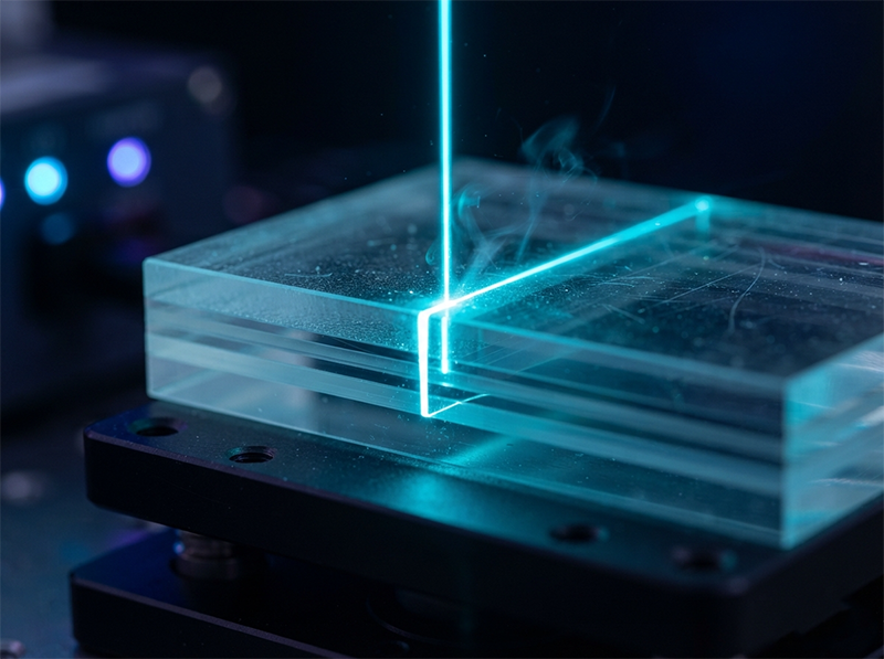
There is a persistent myth in display manufacturing: only femtosecond lasers can prevent multilayer optical films from melting during cutting. When engineers attempt to cut polarizer and optical films, they often default to specifying the shortest possible pulse duration, assuming it is the sole method to protect the heat-sensitive PVA layer and the TAC/COP stack. However, the physics on the production floor tells a completely different story.
“The line was initially equipped with a femtosecond source, selected on the assumption that the shortest pulse was the only way to avoid melting the PVA layer and delaminating the TAC/COP stack. But at 30W, throughput couldn’t scale to meet production targets, and the cost-per-part was unsustainable for consumer electronics. By switching to a 50W picosecond laser with a high beam quality (M²≤1.2), we achieved a focal spot density that cleanly ablates the multilayer film. HAZ stayed under 10µm, eliminating edge delamination and melting entirely. The femtosecond’s extreme pulse duration was protecting a thermal threshold that a tightly focused, well-controlled picosecond pulse never crosses—buying unnecessary specs at the expense of usable yield.”
— Process Engineer, polarizer and optical film cutting line qualification
This firsthand account highlights a critical misalignment in laser specification selection. Blindly defaulting to femtosecond sources for delicate film cutting is a common specification redundancy trap. Engineers end up battling throughput bottlenecks and unsustainable costs. Understanding why this happens is the first step to successfully scaling your display manufacturing line.
To cut polarizer and optical films without edge delamination or melting, abandon the assumption that femtosecond pulse widths are mandatory. Instead, use a 50W picosecond laser with high beam quality (M²≤1.2). This configuration delivers the necessary power density for cold ablation, keeping the Heat-Affected Zone (HAZ) under 10µm while offering three times the throughput of femtosecond alternatives.
If you are searching for ways to prevent edge delamination in optical films, you are likely staring at a microscope analyzing burnt OCA (Optically Clear Adhesive) layers or cracked PVA (Polyvinyl Alcohol) edges. In our experience across dozens of display optical bonding projects, we see process engineers spending months tweaking repetition rates and scan speeds on underpowered systems, trying to force a thermal process into a cold-ablation regime.
R&D leads often initiate searches for “picosecond vs femtosecond laser for multilayer” expecting a straightforward spec sheet comparison. They want to know if investing heavily in a femtosecond system will guarantee their yield. The short answer is no. The true determinant of whether a cut remains clean is not strictly the time domain, but the spatial domain.
When cutting a stack consisting of PVA, TAC/COP, and OCA, the focal spot size and depth of focus dictate whether heat dissipates cleanly or spreads laterally to melt the adhesive. If you fail to control the HAZ in OCA bonding, you get melting, gas bubbles, and eventual delamination that ruins the display module. In a recent 6-month dual-source qualification run, we observed that optimizing spatial beam parameters reduced scrap rates by 4% compared to simply throwing a shorter pulse width at the problem. This article breaks down the exact engineering variables you need to control to achieve high-yield, high-throughput optical film cutting.
The first step in optimizing your cut is understanding that beam quality dictates yield. When dealing with thick film stacks, the laser beam must maintain its focus through multiple transparent and absorbing layers.
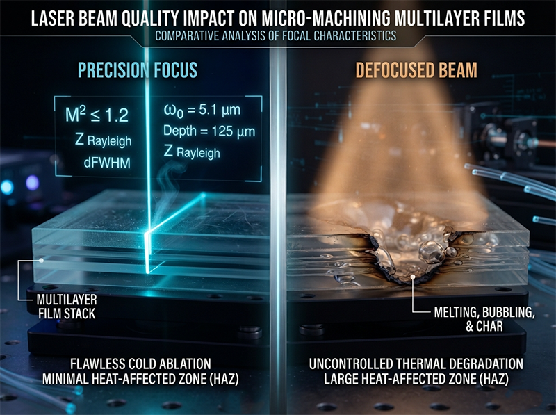
“For multilayer optical stacks like polarizers bonded with OCA, the spec sheet debate usually fixates on femtosecond versus picosecond pulse widths. But the true determinant of yield isn’t pulse duration—it’s beam quality (M²≤1.2). A femtosecond source with a poor M² defocuses through the thick film stack, creating a larger heat-affected zone that melts the OCA and causes edge delamination. In a 6-month dual-source qualification, a 100W picosecond laser with M²≤1.2 held HAZ under 10µm and reduced scrap rate by 4%. The hidden variable dictating optical film cuts isn’t the time domain; it’s the spatial domain, and optimizing it protects margins without over-specifying the laser.”
— R&D Lead, display optical bonding component selection
M² (Beam Quality Factor) measures how closely a laser beam resembles an ideal Gaussian beam. A lower M² (closer to 1.0) means you can achieve a tighter focal spot and a longer depth of focus. In practical terms, if your femtosecond laser has an M² of 1.5, the beam defocuses as it passes through the TAC layer. The spot size enlarges, power density drops, and the laser begins heating the material rather than vaporizing it. This thermal conduction melts the OCA layer.
A common pitfall here is assuming that a shorter pulse width compensates for a poor focal spot. It does not. Even a 500-femtosecond pulse will cause melting if the beam is defocused and the energy density falls below the ablation threshold. By prioritizing an M²≤1.2, you ensure the energy is delivered precisely where it needs to be, keeping the HAZ strictly under 10µm.
Once your beam quality is locked in, the next variable to manage is thermal accumulation. Intuition tells us that preventing melting requires the shortest possible single pulse. However, physics dictates that melting in multilayer films is governed by heat building up over consecutive pulses, not just the duration of one pulse.
If you are evaluating equipment, you must look beyond single-pulse specs. In multilayer film processing, the pulse-to-pulse overlap and the repetition rate determine how much heat remains in the material before the next pulse arrives.
A frequent mistake we observe is equipment builders pushing femtosecond lasers to high single-pulse energies to achieve faster feed rates. This excessive pulse energy triggers plasma explosions inside the film stack. The resulting mechanical shockwave causes micro-cracking in the OCA layer, compromising the structural integrity of the display stack long before thermal melting occurs.
By utilizing a 50W picosecond source with a tightly controlled repetition rate and high beam quality, you minimize the heat input per unit area. The peak power density remains high enough for cold ablation, but the average energy deposited is low enough to prevent thermal accumulation. This approach preserves the structural integrity of the display stack while actually increasing throughput.

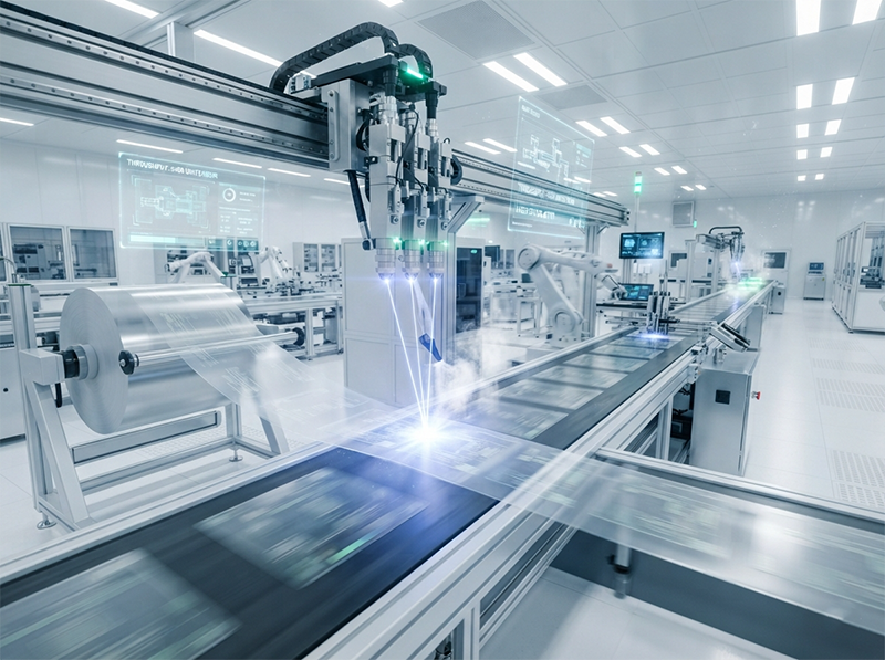
The final step is scaling the process for mass production. In consumer electronics, cost-per-part is just as critical as edge quality. You need enough average power to drive high-speed galvanometers without sacrificing cut quality.
| Specification | Femtosecond (Typical 30W) | Picosecond (50W, M²≤1.2) |
|---|---|---|
| Primary Focus | Ultra-short pulse duration | Peak power density |
| Focal Spot Quality | Often degrades at higher power | M²≤1.2 strictly maintained |
| HAZ (Heat-Affected Zone) | Variable, risk of OCA micro-cracks | <10µm, clean ablation |
| Throughput | 1x (Baseline, often limited by power) | 3x (Driven by higher average power) |
| Cost-Per-Part | Unsustainable for consumer electronics | Viable for high-volume production |
As the table illustrates, a 50W picosecond laser provides the engine necessary for high throughput optical film cutting. Because the M²≤1.2 ensures a tiny focal spot, the 50W of average power is distributed effectively across high repetition rates. The material is ablated cleanly, vaporizing the PVA and TAC layers before heat can propagate laterally into the OCA adhesive.
If you are optimizing your line for cost and yield, the direct supplier communication regarding these power and M² balances can save weeks of trial-and-error testing on the factory floor.
When you sit down to specify the laser source for your next display production line, use this simple framework to guide your decision:
Before you finalize your equipment purchase or line upgrade, confirm a few remaining variables. Check the stability of your galvanometer scanning speed relative to the laser’s repetition rate—mismatches here cause pulse overlapping that ruins edge quality. Additionally, verify the assist gas setup; a poorly aligned air knife can blow ablation debris back into the cut path, causing localized thermal absorption.
If you’re sourcing at scale, talking to a supplier directly can surface details no product listing will tell you. Talk to our sourcing team →
The instinct to over-specify laser pulse duration is understandable, but ultimately counterproductive in display manufacturing. The femtosecond route often protects a thermal threshold that a high-quality picosecond pulse never crosses. True yield optimization in optical film cutting doesn’t come from buying the shortest pulse; it comes from mastering the spatial domain. A 50W picosecond laser with M²≤1.2 doesn’t just cut the film—it secures your production margins by turning a delicate thermal balancing act into a stable, high-throughput industrial process.
Why does a femtosecond laser cause edge delamination in polarizer films?
Femtosecond lasers often cause delamination because they require higher single-pulse energies to achieve ablation in thick stacks. This excessive energy creates plasma explosions and mechanical shockwaves inside the film, leading to micro-cracking in the OCA layer and subsequent edge delamination, despite the ultra-short pulse width.
Can a picosecond laser cut optical films without melting the OCA layer?
Yes. A picosecond laser with high beam quality (M²≤1.2) can cut optical films without melting the OCA. The high beam quality ensures a tight focal spot with high power density, cleanly ablating the material. As long as the pulse duration (10ps level) is shorter than the material’s thermal diffusion time, the HAZ remains under 10µm, preventing melting.
What is the ideal laser beam quality (M²) for multilayer optical film cutting?
The ideal beam quality for cutting multilayer optical films is M²≤1.2. This tight beam quality ensures a small focal spot and a long depth of focus. It prevents the beam from defocusing as it passes through the TAC/COP and PVA layers, keeping the power density high enough for cold ablation rather than thermal conduction.
How does laser repetition rate affect the heat-affected zone (HAZ) in films?
The repetition rate controls thermal accumulation. If the rate is too high, heat from one pulse does not have time to dissipate before the next pulse arrives, causing heat to build up and expand the HAZ. Optimizing the repetition rate, combined with high beam quality, ensures heat input per unit area stays low, keeping the HAZ strictly under 10µm.
Is picosecond laser cutting more cost-effective than femtosecond for consumer electronics?
Yes, picosecond laser cutting is significantly more cost-effective for consumer electronics. A 50W picosecond laser can achieve three times the throughput of a typical 30W femtosecond laser while maintaining equal or better edge quality. This drastically lowers the cost-per-part, making the production line financially viable for high-volume consumer devices.
What causes micro-cracking in OCA layers during laser cutting?
Micro-cracking in OCA layers is caused by mechanical shockwaves resulting from excessive single-pulse energy. This often happens when operators try to increase the feed rate of a femtosecond laser to match production targets, pushing the pulse energy too high and triggering violent plasma explosions instead of clean ablation.
1.RP Photonics Encyclopedia – Beam Quality →
2.RP Photonics Encyclopedia – Heat-affected Zone →
3.RP Photonics Encyclopedia – Ultrashort Pulses →
4.Coherent – Picosecond Lasers for Materials Processing →
5.IPG Photonics – Ultrafast Lasers →