Speed gets the blame for almost every precision failure in laser micromachining. Push the repetition rate higher, the reasoning goes, and thermal accumulation builds, the HAZ widens, kerf edges chip, and the careful process window established in qualification quietly collapses. It is an intuitive story. It is also, in the majority of production failure cases we have seen, the wrong one.
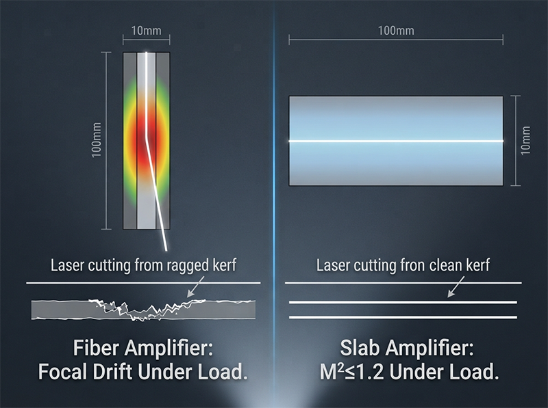
“When pushing laser repetition rates higher to increase SiC wafer dicing throughput, the assumption is that speed introduces thermal accumulation and degrades precision. The actual failure mode is beam drift from thermal lensing. Over-specifying to a high-power femtosecond source to ‘protect’ HAZ often exacerbates this: at high rep rates, the fiber amplifier’s thermal load causes focal shifts, degrading kerf straightness. Switching to a 150W picosecond source with slab amplifier architecture held <0.5% RMS power stability and M²≤1.2, allowing a 2x increase in scanning speed while maintaining <10µm HAZ and ±1µm precision. Throughput didn’t compromise precision; the chosen laser architecture’s thermal management did.”
— process engineer, SiC wafer dicing line expansion
The distinction in that account is not subtle. Throughput itself did not degrade the process. A fiber amplifier operating under high average power load introduced focal drift, and the focal drift degraded kerf straightness. Change the amplifier architecture, and the same throughput target is achievable without touching the precision specification. The variable the team was managing — speed — was not the one setting the damage floor.
Higher throughput does not inherently compromise precision in semiconductor laser processing. Precision failures at high throughput are almost always traceable to one of three specific source-level causes: thermal lensing from amplifier architecture mismatch, operating a laser outside its stable power window to hit a peak specification, or fixed-frequency pulse delivery that loses synchronization with high-speed motion control. Each of these is a solvable engineering problem, not a physical law.
The throughput-versus-precision framing is one of the most persistent and costly misconceptions in semiconductor laser process engineering. It shapes sourcing decisions, integration specifications, and production scaling strategies — often in the wrong direction. Engineers who accept it as a physical constant end up over-specifying peak power, adding mechanical compensation layers, or limiting scan speeds to a fraction of what the optics can support.
In our experience across SiC wafer dicing, advanced packaging via drilling, and micro-machining workstation integration, the question is never really “how much precision must we sacrifice for speed?” The question is: which parameter in the current setup is actually causing the degradation, and is that parameter a property of the physics or a property of the chosen hardware?
That distinction matters because the two have very different remedies. A physical limit requires a fundamental process redesign. A hardware mismatch requires a source or architecture change — often a far less disruptive intervention. This article works through the three most common hardware-level causes of the throughput-precision failure mode, with engineering data and real integration scenarios for each.
Thermal lensing is a well-characterized phenomenon in laser physics: as average power increases in an amplifier medium, thermal gradients build across the gain material, creating a refractive index gradient that acts like a weak lens. The focal point shifts. For a fixed optical path, that shift means the beam arrives at the workpiece with a different spot size and a different fluence than the recipe specifies.
In a fiber amplifier running at high repetition rates and high average power, the thermal load per unit volume of gain medium is high[1]. The core diameter is small, heat is deposited rapidly, and the thermal gradient is steep. Focal shift under these conditions is not a worst-case scenario — it is the predictable steady-state behavior. M² values that measure at 1.1 at low power drift toward 1.3–1.5 under full thermal load, and kerf straightness degrades accordingly.
A slab amplifier distributes the same thermal load across a larger gain volume. The thermal gradient per unit length is lower, and the resulting lensing effect is substantially reduced. In the SiC dicing case above, switching to a 150W picosecond source with slab architecture held M²≤1.2 and <0.5% RMS power stability at full operating load. The 2× scanning speed increase was not achieved by tolerating more thermal damage — it was achieved by eliminating the focal drift that had been the actual bottleneck.
Common Mistake: Selecting a femtosecond source specifically to reduce HAZ on wide-bandgap materials, then operating it at high repetition rates in a fiber amplifier configuration. The femtosecond pulse duration delivers cold ablation in principle. The fiber amplifier’s thermal behavior under high average power load negates that advantage at the system level.
The practical implication: when evaluating laser sources for high-throughput SiC or GaN wafer dicing, M² stability under full thermal load — not the cold-start M² on the spec sheet — is the parameter that determines in-production precision.
The second cause is closely related but operates at a different level. It is not about focal drift — it is about pulse-to-pulse energy fluctuation when a source is pushed toward or beyond its stable operating envelope.
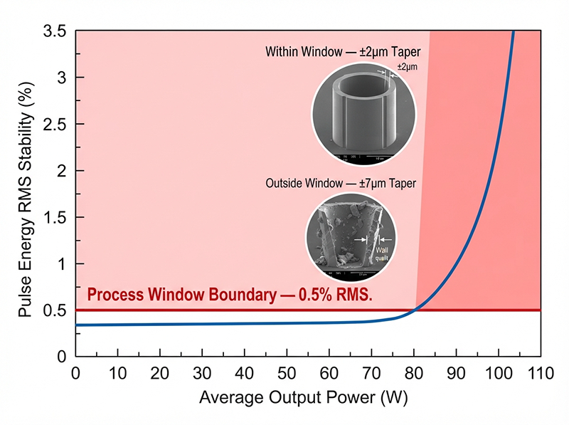
“In semiconductor advanced packaging, the trade-off between throughput and precision is treated as a physical constant. It is not — it is a bandwidth limitation. Attempting to scale a 50W femtosecond system to 100W often pushes the laser out of its stable operating window, causing pulse-to-pulse energy fluctuations that destroy via uniformity in TGV drilling. The counterintuitive move was avoiding the peak-power arms race. By utilizing a 100W picosecond laser with <0.1nm spectral linewidth and <0.5% RMS long-term stability, we matched the throughput target while holding via taper within ±2µm. The precision wasn’t lost to speed; it was lost to operating an unstable source outside its thermal sweet spot just to hit a power spec.”
— R&D lead, semiconductor packaging process qualification
Through-glass via (TGV) drilling is a precision-critical application. Via taper, depth uniformity, and sidewall roughness are all direct functions of pulse energy consistency. If pulse energy fluctuates by even 2–3% across a drilling sequence, the ablation threshold is crossed inconsistently[2]: some pulses remove material above threshold, others hover near it. The cumulative effect is via taper variation, sidewall striations, and depth inconsistency that fails the interconnect specification.
The failure mode described here — scaling a 50W femtosecond system to 100W and encountering pulse instability — is a known behavior in solid-state and fiber laser architectures. Every gain medium has a thermal sweet spot: a power range over which inversion density, thermal gradient, and output coupling are in equilibrium. Pushing beyond that range introduces gain saturation dynamics and thermal instability that manifest as pulse energy jitter. The <0.5% RMS long-term stability figure is not a cosmetic specification — it is the threshold below which TGV depth uniformity is maintainable at production scale.
| Parameter | 50W → 100W Scaled Femtosecond | 100W Picosecond (Stable Window) |
|---|---|---|
| Pulse Energy Stability | >2% RMS (outside thermal sweet spot) | <0.5% RMS |
| Via Taper Variation | ±5–8µm | ±2µm |
| Spectral Linewidth | Broadened under thermal load | <0.1nm |
| Operating Risk | Gain saturation, thermal runaway | Within designed envelope |
| Throughput Achieved | Limited by instability-induced rework | Full target met |
The sourcing lesson is direct: a laser’s rated peak power is the output at its best operating condition. The question that determines production suitability is how stability behaves as average power climbs toward that rating — and whether the architecture was designed to operate continuously at that load.
If you’re specifying a picosecond or femtosecond source for TGV or high-density via drilling, ask for the RMS power stability curve at 80%, 90%, and 100% of rated power, not just the headline figure.
The third cause operates entirely at the system integration layer, and it is the one most frequently overlooked in source-level evaluations. It does not involve HAZ, focal drift, or pulse energy. It involves timing.
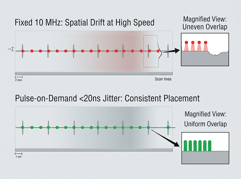
“Integrating a laser into a high-throughput semiconductor cutting station usually forces a compromise: run the scanner faster, and pulse overlap drops, ruining edge quality. The bottleneck isn’t the laser’s precision, but the synchronization between the trigger and the galvo. A rigidly pulsed 100W laser firing at a fixed 10 MHz will spatially drift at high scan speeds. Upgrading to a laser with pulse-on-demand and <20 ns timing jitter allowed synchronization with the scanner at 3 MHz. This achieved a 3x throughput jump with zero loss in spatial pulse placement accuracy. The trade-off wasn’t throughput vs. precision; it was fixed-frequency operation vs. intelligent pulse delivery.”
— system integrator, semiconductor micro-machining workstation development
A laser firing at a fixed repetition rate — 10 MHz, for example — places pulses at spatial intervals determined by the scan velocity at the moment of firing[3]. At low scan speeds, the pulse-to-pulse spacing is consistent and overlap is predictable. As scan speed increases, the spatial drift between trigger timing and actual beam position accumulates. At high scan speeds, pulses land where the beam was, not where it is. The result is non-uniform pulse overlap, irregular material removal per pass, and edge quality that degrades progressively with scan velocity.
Pulse-on-demand (POD) architecture inverts this relationship. Instead of the laser dictating when pulses fire, the motion controller dictates it. The galvo system fires the laser at the precise moment the beam is at the target spatial coordinate. With timing jitter below 20 ns, spatial pulse placement accuracy is maintained regardless of scan speed. The 3× throughput increase described above was not achieved by improving beam quality or increasing power — it was achieved by changing the control architecture so that speed no longer introduced positional error.
This has direct implications for how integration engineers should evaluate laser sources. For high-throughput micro-machining workstations, pulse-on-demand capability and timing jitter specification are as critical as M² and pulse duration. A source without POD capability will impose a scan speed ceiling that no optical or mechanical improvement can overcome.
Use this framework to identify which cause applies to your throughput-precision failure mode — and what intervention addresses it:
In none of these cases is the root cause “throughput.” In all three, it is a specific, identifiable hardware or architecture parameter that has a direct engineering remedy.
The throughput-precision relationship in semiconductor laser processing is not a fixed constraint — it is a function of which parameters are limiting your specific process in your specific architecture. Before committing to a source specification, it is worth confirming three things: the M² stability figure your supplier quotes is measured at full operating load, not cold start; the power stability specification is given as RMS over the full rated power range, not just at one operating point; and the source’s trigger interface supports the synchronization architecture your motion controller requires.
These details will not appear on a standard spec sheet. If you are sourcing at scale, talking to a supplier directly can surface details no product listing will tell you.
Throughput and precision have been treated as opposing forces in semiconductor laser processing for long enough that the trade-off feels like physics. It is not. The engineers who achieve 2× and 3× throughput gains without sacrificing precision are not working around a fundamental limit — they are solving for the specific hardware variable that was actually causing the degradation: an amplifier architecture that introduces focal drift under load, a source pushed past its stable operating window to hit a power spec, a fixed-frequency trigger that loses synchronization with a fast-moving galvo. Fix the right variable, and speed stops being the enemy of precision. The trade-off was never between throughput and quality — it was always between understanding your failure mode and not understanding it.
Does increasing laser repetition rate always increase thermal damage in semiconductor processing?
Not necessarily. Thermal damage at higher repetition rates depends on whether heat can dissipate between pulses — a function of material thermal diffusivity, pulse energy, and spot size — but also on whether the laser source maintains beam quality under the higher average power load. A source with good thermal management in its amplifier architecture can increase rep rate without a proportional increase in HAZ.
What is thermal lensing in a laser amplifier and why does it affect precision?
Thermal lensing occurs when a temperature gradient builds across the gain medium, creating a refractive index variation that acts as a weak lens. This shifts the focal position of the output beam. In production laser processing, a focal shift of even 0.1–0.3 mm can move the process outside its low-damage fluence window, widening HAZ and degrading kerf straightness. It is a predictable consequence of high average power operation in gain media with poor thermal conductivity, particularly in fiber amplifiers.
Why might a femtosecond laser perform worse than a picosecond laser at high throughput?
At high repetition rates and high average power, the fiber amplifier architectures commonly used in femtosecond systems develop significant thermal loads. This introduces M² degradation and focal drift that offsets the pulse-duration advantage of femtosecond operation. A picosecond source with slab amplifier architecture can maintain lower M² and higher power stability under the same operating conditions, making it more suitable for high-throughput applications where consistent beam quality matters more than the shortest possible pulse duration.
What does pulse-on-demand mean in laser processing, and when is it necessary?
Pulse-on-demand (POD) is a laser triggering architecture where the motion controller, rather than the laser’s internal clock, determines when each pulse fires. This ensures pulses land at the correct spatial coordinate regardless of scan speed. It is necessary in high-speed micro-machining applications where fixed-frequency operation would cause spatial drift between the trigger event and the actual beam position, degrading pulse overlap uniformity and edge quality.
How do I evaluate laser power stability for a high-throughput semiconductor application?
Request the RMS power stability figure across the full rated power range — specifically at 80%, 90%, and 100% of rated average power — measured over a representative operating period (typically 1–8 hours). A figure of <0.5% RMS over that range indicates the source is operating within its thermal sweet spot. Figures above 1.5% RMS at high power settings suggest the source is approaching or exceeding its stable operating envelope, with the risk of pulse energy fluctuations that will compromise process uniformity.
What is the difference between M² at cold start and M² under full thermal load?
M² (beam quality factor) measures how close a laser beam is to a perfect Gaussian profile, where M²=1.0 is ideal. Cold-start M² is measured immediately after the laser is switched on, before thermal equilibrium is reached in the amplifier. Under full thermal load — after minutes to hours of operation at rated power — thermal lensing can degrade M² by 0.1–0.4 units in fiber amplifier architectures. For precision laser processing, the in-production M² under full thermal load is the operationally relevant figure, not the cold-start specification.
Can synchronization improvements alone achieve throughput gains without changing the laser source?
In some cases, yes — but with limits. If the current bottleneck is trigger-galvo synchronization loss from fixed-frequency operation, upgrading the motion controller’s trigger interface or adding a pulse picker can improve spatial accuracy at higher scan speeds. However, if the laser source itself does not support pulse-on-demand with low timing jitter (<20 ns), the system-level synchronization architecture cannot fully compensate. The most effective solution addresses both the source’s trigger capability and the motion controller’s synchronization logic simultaneously.
[Author Bio Placeholder]
About the Author: The [Brand Name] applications engineering team works with process engineers, R&D leads, and system integrators across semiconductor wafer dicing, advanced packaging, and precision micro-machining. Our focus is on matching laser source architecture to production process requirements — with particular attention to the parameters that govern yield at volume, not just at qualification.
[1] “Evidence of thermal effects in high power Er”. Peer-reviewed reviews of high-power rare-earth-doped fiber lasers describe quantum-defect absorption and nonradiative losses as volumetric heat sources, and explain that high average power in small fiber geometries can produce substantial temperature gradients. Evidence role: mechanism; source type: paper. Supports: In high-repetition-rate, high-average-power fiber amplifiers, the thermal load per unit volume of gain medium is high.. Scope note: This supports the physical mechanism and scaling of thermal load, not a specific heat-load value for the described amplifier.
[2] “Intensity Modulation Effects on Ultrafast Laser Ablation Efficiency …”. Laser ablation literature defines material removal as occurring when incident fluence exceeds a material-specific ablation threshold, providing context for why pulse-to-pulse energy variation near that threshold can alter removal behavior. Evidence role: mechanism; source type: paper. Supports: Pulse energy fluctuations near the ablation threshold can cause inconsistent material removal during laser drilling.. Scope note: A general ablation-threshold source would substantiate the threshold mechanism, but the specific 2–3% tolerance should be supported by TGV-specific experimental data if the article intends it as a quantified limit.
[3] “Pulse-on-Demand Operation for Precise High-Speed UV Laser …”. A source on pulsed-laser scanning or laser micromachining can support that, for a fixed pulse repetition frequency, the distance between successive pulses is governed by scan speed divided by repetition rate. Evidence role: mechanism; source type: paper. Supports: In fixed-repetition-rate laser scanning, pulse-to-pulse spatial spacing is determined by the beam scan velocity at the time of firing.