
The pressure on consumer electronics production lines is relentless. When a major brand demands a 3x increase in cover glass output for their next flagship phone, the first instinct is to push the existing machinery faster. Increase scanner speeds, optimize motion paths, shave milliseconds off every step. Yet, for many, the line hits a hard wall. The Units Per Hour (UPH) flatline, and worse, final yield starts to drop. The bottleneck, it turns out, is not the speed of any single component, but the fundamental design of the entire cutting process.
“The bottleneck in scaling cover glass lines wasn’t the picosecond laser’s cutting speed; it was the industry’s reliance on a CO₂ thermal splitting step to finish the cut. A standard 70W picosecond source scribes the groove, but lacks the pulse energy to cleave 1mm aluminosilicate glass cleanly, forcing the addition of a CO₂ module. That secondary thermal process introduces edge stress, drops chemical tempering yield by 4-6%, and caps the line at a single beam. By switching to a 300W picosecond source with >300μJ pulse energy, the Bessel beam achieves clean self-cleavage in a single dry pass. The high average power then splits into 3 parallel beams, lifting UPH by 3x while eliminating CO₂-related tempering failures. The variable limiting throughput wasn’t scanner speed; it was the unnecessary second laser.”
— Equipment Integrator, smartphone cover glass production line design
This integrator’s discovery is a paradigm shift for the industry. The established two-laser process, long considered a necessary compromise, is now the primary obstacle to true scalability. The pursuit of higher throughput isn’t about incremental speed gains; it’s about eliminating an entire process step. This insight reveals that the key to unlocking massive output gains lies not in pushing old methods harder, but in adopting a technology that makes them obsolete.
Scaling cover glass throughput requires replacing the slow, complex, and yield-damaging two-step “picosecond scribe + CO₂ split” process. The solution is a single-step method using a high-power picosecond laser for cover glass processing. A 300W source with high pulse energy (>300μJ) and Bessel beam shaping enables “self-cleavage,” where the glass separates cleanly in a single pass. The high average power can then be split into multiple parallel beams, directly multiplying UPH by 3x or more.
If you are an equipment integrator, R&D lead, or process engineer in the consumer electronics supply chain, you are living this challenge daily. You’re being squeezed by the world’s largest tech brands to deliver millions of perfectly cut and strengthened glass components at an ever-lower cost per part. The conventional dual-laser approach is failing to meet these demands.
In our experience integrating laser systems for top-tier consumer electronics lines, we have seen the hidden costs of this “standard” process firsthand. The obvious costs are the bill of materials (BOM) for the CO₂ laser and the additional factory floor space. The hidden, more damaging costs are the complex optical alignment of two separate laser systems and, most critically, the 4-6% yield loss that occurs during chemical tempering due to thermal stress from the CO₂ laser. This article will deconstruct why the dual-laser approach fails at scale, explain the physics behind the superior single-laser solution, and provide a clear framework for designing the next generation of high-throughput glass cutting lines.
The industry standard for cutting aluminosilicate glass (like Corning’s Gorilla Glass) has long been a two-step process. First, a low-power picosecond laser scribes a precise groove. Second, a CO₂ laser follows the path, applying intense thermal shock to propagate a crack and separate the part. While functional, this method is fundamentally flawed for high-volume manufacturing.
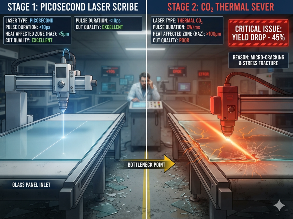
The core issue is heat. A picosecond laser is chosen for its “cold” ablation quality, but the subsequent CO₂ splitting step reintroduces a massive, uncontrolled thermal element right at the critical edge. This heat induces stress and micro-defects that are often invisible post-cutting. The real damage only becomes apparent later.
“The assumption was that adding a CO₂ laser to a picosecond line was necessary to ensure clean cleavage on 0.5mm smartwatch glass. In reality, the thermal stress from the CO₂ module was the exact cause of microcracks discovered during tempering. A 300W picosecond source, utilizing Bessel beam filamentation, deposits energy nonlinearly inside the glass. The resulting plasma channel induces a stress field that separates the glass through pure mechanical self-cleavage, leaving an edge with Ra < 0.5μm and zero HAZ. Dropping the CO₂ laser entirely not only simplified optical alignment but eliminated the thermal defect root cause, pushing tempering yield to 99.2%. The quality leap came from removing a laser, not adding one.”
— R&D Lead, wearable cover glass process qualification
This R&D lead’s experience proves that the CO₂ laser is not an aid; it’s the culprit. It creates the very flaws that cause parts to fail during the final chemical strengthening stage, directly hurting the all-important final yield and driving up the effective cost per part.
The dual-laser process is inherently serial. You must scribe then split. This, combined with the fact that it’s difficult to perfectly align multiple CO₂ beams with multiple scribe beams, means most lines are stuck with a single processing path. You can make the scanner move faster, but you can’t change the fact that you are processing one part at a time. This creates a hard, physical ceiling on your maximum Units Per Hour.
If your production goals require you to break through this ceiling, you need a different method. This is where high-power picosecond lasers for cover glass come in.
The new paradigm is to perform the entire cutting and separation process in a single step using a single laser. This is made possible by combining two key technological advancements: high pulse energy and sophisticated beam shaping.
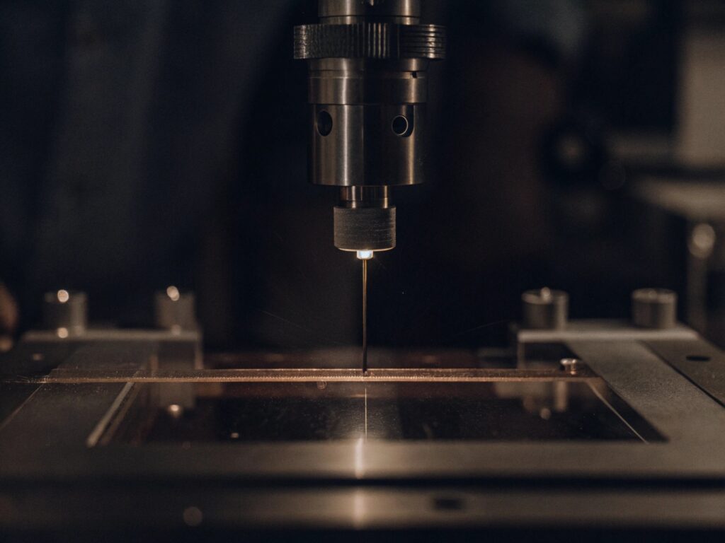
To achieve single-pass separation, the laser must create a modification not just on the surface, but through the entire thickness of the glass. This requires a laser with high single-pulse energy, typically greater than 300μJ.
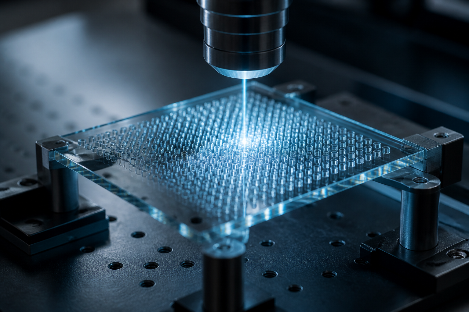
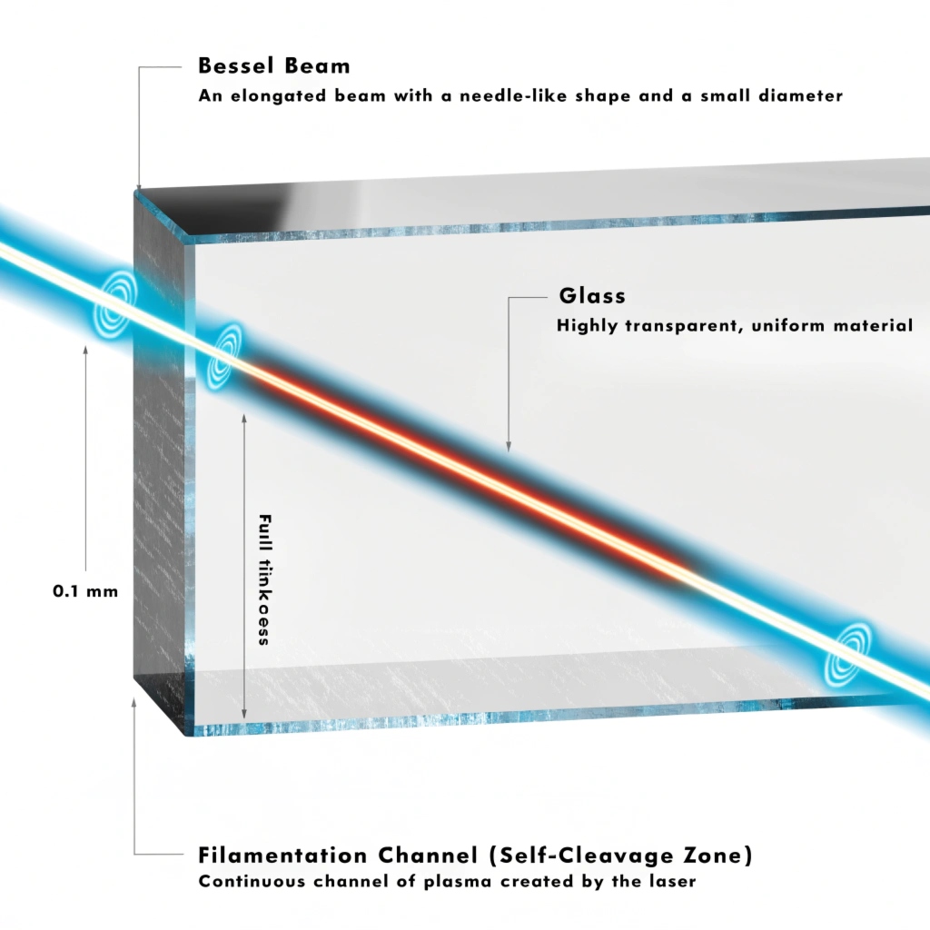
This high-energy pulse is then shaped into a Bessel beam. Unlike a standard focused beam which has a tiny focal spot, a Bessel beam creates an elongated, needle-like focal zone that can be several millimeters long. When this high-intensity needle of light passes through the glass, it triggers a nonlinear absorption process called filamentation. This creates a continuous plasma channel, like a microscopic perforation, inside the material.
This internal plasma channel induces a highly localized, uniform stress field. The stress is sufficient to cause the glass to cleave along the perforation line—a process known as picosecond laser self-cleavage. Because the energy is deposited inside the material and the separation is mechanical, there is virtually zero heat-affected zone (HAZ) and the resulting edge quality is pristine (surface roughness Ra < 0.5µm).
Achieving single-pass cleavage is only half the solution. The other half is multiplying this effect. A single self-cleavage pass doesn’t require the full 300W of average power. The excess power is what enables massive parallelization.
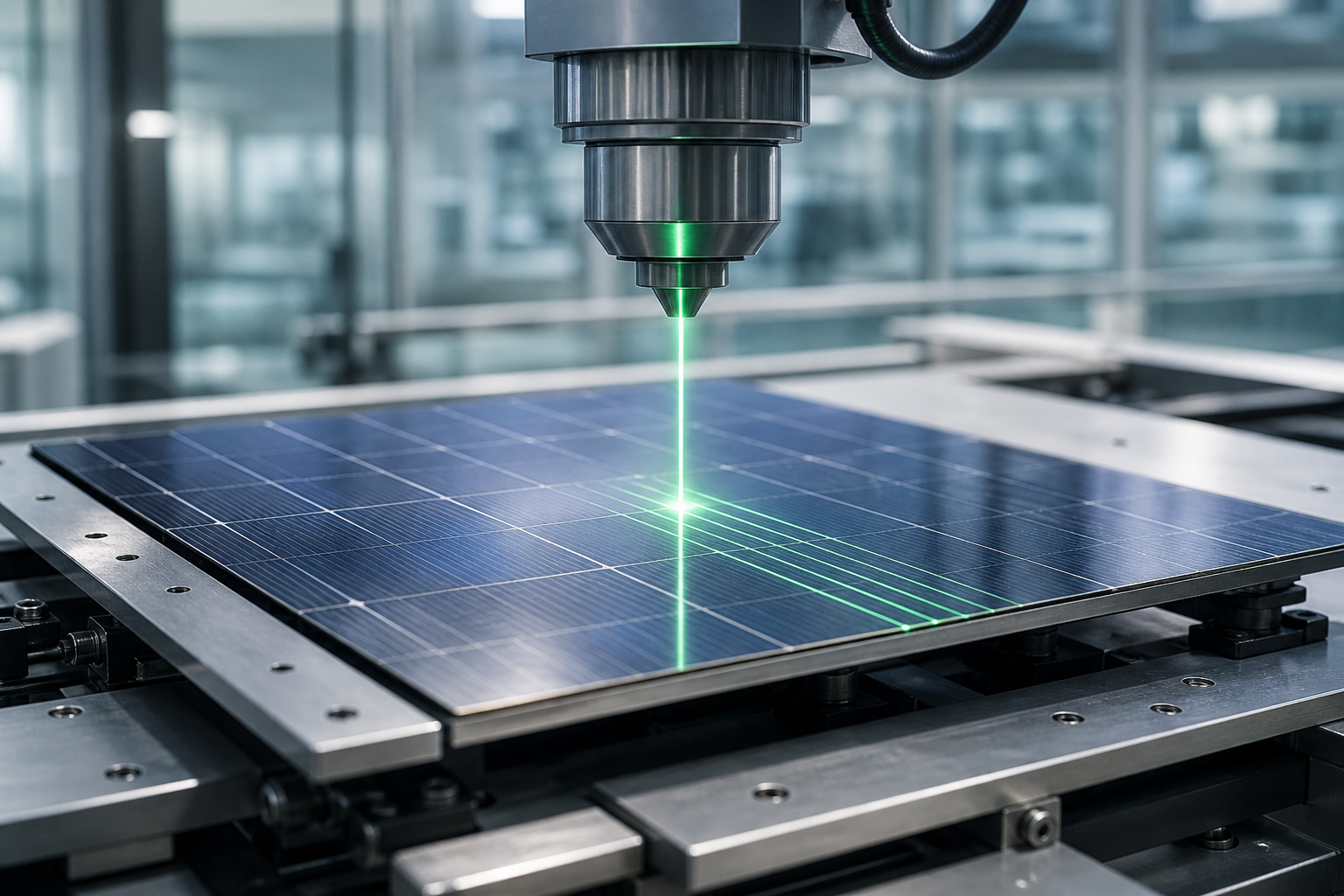
A high-power 300W picosecond laser beam can be passed through a Diffractive Optical Element (DOE), which acts as a beam splitter. It divides the single input beam into 3, 5, or even more identical, lower-power beams. Each of these beams can be directed by the scanner system to perform the same single-pass self-cleavage process on different parts simultaneously.
This is how you break the UPH ceiling. Instead of processing one part at a time, you are now processing three or more. The result is a direct multiplication of throughput, all while improving quality and reducing system complexity.
| Metric | Traditional “Picosecond + CO₂” Process | High-Power Picosecond Self-Cleavage |
|---|---|---|
| Process Steps | 2 (Scribe + Thermal Split) | 1 (Single Pass) |
| Lasers Required | 2 (Picosecond + CO₂) | 1 (High-Power Picosecond) |
| Parallel Processing | Not Feasible (Single Beam) | Standard (e.g., 3-5 Beams) |
| Edge Quality (Ra) | >1.0µm, with thermal stress | <0.5µm, zero HAZ |
| Tempering Yield Impact | -4% to -6% yield loss | Negligible impact, >99% yield |
| Typical UPH | X | 3X or more |
When specifying the laser system for a new cover glass production line, use this framework to ensure you are building for the future, not repeating the mistakes of the past.

The transition to a single-laser process is a strategic advantage. However, the optimal parameters—pulse energy, number of split beams, and scanning strategy—depend on the specific glass type, thickness, and desired edge quality. These are variables best confirmed through application testing. A proof-of-concept trial can de-risk the integration and provide hard data on the achievable UPH and yield for your exact product.
If you’re sourcing at scale, talking to a supplier directly can surface details no product listing will tell you.
The industry’s long reliance on the two-laser method for cutting cover glass was never an ideal solution; it was a clever workaround for the limitations of older laser technology. The arrival of robust, industrial-grade 300W picosecond lasers has rendered that workaround obsolete. The new bottleneck isn’t speed, but process complexity. True scalability in cover glass manufacturing isn’t achieved by making one step faster, but by eliminating an entire step from the process.
Why not just use a more powerful CO₂ laser for cutting glass?
A CO₂ laser cuts with intense thermal energy. While effective for thick, non-precision cutting, it induces significant thermal stress and micro-cracks in thin cover glass. This damage leads to catastrophic failure during the subsequent chemical strengthening (tempering) stage. Picosecond lasers cut with a “cold” process, preserving the material’s integrity and maximizing final yield.
What is the minimum pulse energy for picosecond laser self-cleavage?
The required pulse energy depends on the glass thickness and type, but for typical aluminosilicate cover glass up to 1mm thick, a single-pulse energy of >300µJ is generally required to create a full-depth filament for clean self-cleavage. A laser with lower pulse energy cannot achieve this in a single pass.
Is a 300W picosecond laser overkill for thin wearable glass?
No. While less pulse energy might be needed for thinner glass, the high average power of a 300W source is what allows for aggressive beam splitting. You can divide the 300W into 5 or more beams to process multiple small wearable components simultaneously, dramatically increasing your Units Per Hour (UPH) far beyond what a lower-power laser could achieve.
Why not use a cheaper 50W picosecond laser and just scan multiple times?
“At 50W, the pulse energy was insufficient for full-depth filamentation in 0.7mm cover glass, requiring multiple passes. This caused debris accumulation and inconsistent cleavage. The shift to a 300W picosecond laser didn’t mean cutting faster; it meant cutting once. The high pulse energy created a continuous modification channel in a single pass.”
— Process Engineer
This multi-pass approach is slower and creates debris, which can redeposit on the edge and compromise quality. A single, clean pass with high pulse energy is both faster and produces a higher quality result.
What is a Bessel beam and why is it important for glass cutting?
A Bessel beam is a special type of laser beam that is shaped to have a long, narrow focal zone, like a needle of light. This shape is critical for glass cutting because it allows the laser energy to be deposited deep inside the material in a continuous line (filament), enabling the single-pass self-cleavage process. A standard focused beam cannot achieve this.
How does picosecond self-cleavage improve chemical tempering yield?
Chemical tempering yield is highly sensitive to edge defects. The CO₂ laser in the traditional process creates thermal stress and micro-cracks, which are weak points where failure originates during tempering. Picosecond self-cleavage is a cold, mechanical process that leaves a pristine, defect-free edge, eliminating the root cause of tempering failures and boosting yield by 4-6%.
What is the typical edge roughness (Ra) after self-cleavage?
A well-optimized picosecond laser self-cleavage process can consistently produce an edge with a surface roughness (Ra) of less than 0.5 micrometers. This exceptionally smooth finish often reduces or eliminates the need for subsequent polishing steps, further simplifying the production line and lowering cost.