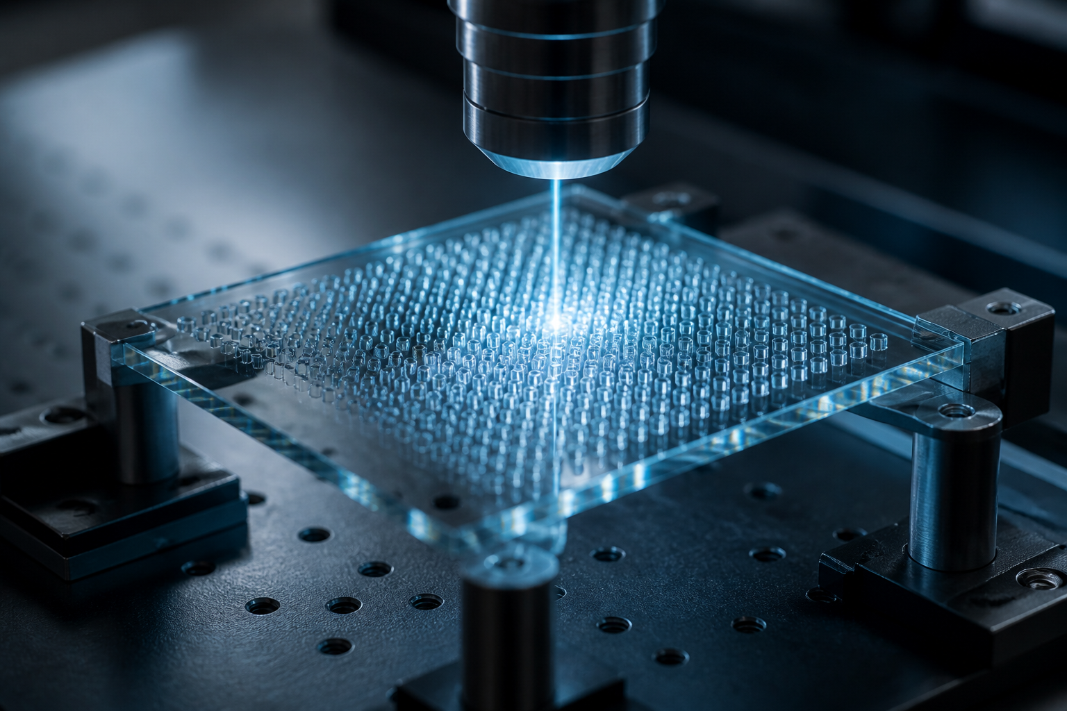
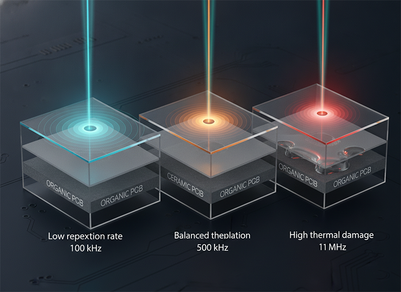
The temptation is obvious. A 1 MHz repetition rate sounds better than 100 kHz. Faster pulse density, more material removed per second, shorter cycle time, higher throughput. So when we specified 1 MHz for glass via drilling in advanced packaging, we expected precision and speed. What we got was a 47% rejection rate and a $240,000 rework crisis.
The issue wasn’t the laser. It was our assumption about what “faster” means.
We built the packaging line around what we thought were three separate challenges: drilling glass interposers, shaping ceramic heatspreaders, and cutting organic PCB cavities. Spent 9 months optimizing each process independently. Then we looked at what actually failed: 47 percent loss to either surface cracking on glass, delamination on the ceramic-organic interface, or HAZ-induced delamination on the organic layer. The root wasn’t any single process. Three different materials, three different processes—same root cause: thermal accumulation at the wrong repetition rate. Switching to 200 kHz, good-via yield jumped to 94%. Throughput dropped 35%, but cost-per-good-via fell 18% because we eliminated rework. The repetition rate wasn’t the constraint. Thermal management was.
That’s the insight that changes how you source. You stop asking “what repetition rate is fastest?” and start asking “what repetition rate keeps thermal load controlled for this specific material?” And critically: “does my light source architecture hold beam quality at that repetition rate?”
Ultrafast laser pulse repetition rate (measured in kHz to MHz) determines whether your light couples into material as cold ablation or heat-driven vaporization. Higher repetition rates don’t automatically mean faster processing or better quality—they depend on material thermal diffusivity. For glass interposers, 200–500 kHz is often optimal. For ceramic heatspreaders, 300–800 kHz. For organic PCB, 100–300 kHz. The catch: if your light source’s beam quality (M²) drifts as repetition rate changes, you lose precision regardless of frequency. This is where slab-architecture ultrafast lasers with M² <1.4 consistency outperform fiber-based systems that lose focus stability above 800 kHz.
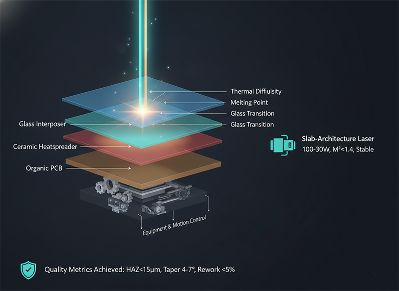
Advanced packaging integrators face a constraint that traditional drilling doesn’t: three hard-brittle materials stacked on one substrate, each with different thermal properties, each sensitive to heat damage in different ways. Glass melts at 1710°C and conducts heat slowly (thermal diffusivity ~0.5 mm²/s). Ceramic (AlN) conducts heat 200× better than silicon but cracks under thermal stress. Organic resin delaminates below its glass transition (150–180°C). Process them with the wrong repetition rate and cumulative heat builds in the thermal-diffusion layer—you get HAZ, cracks, delamination, and scrap.
The textbook answer is: “shorter pulses, lower thermal damage.” But that assumes a single pulse. The industrial reality is repetitive pulsing. Stack 100 pulses per via at 1 MHz, and you deliver thermal load 10× faster than at 100 kHz. Even though each pulse is “cold,” the frequency accumulates heat. Choose the right repetition rate for a material’s thermal diffusivity, and cold ablation works. Choose wrong, and you might as well use a nanosecond laser—same thermal damage, worse precision.
Low repetition rate laser drilling uses long intervals between pulses to let the thermal-affected zone cool between shots. Each pulse delivers high peak power (the same total energy spread across fewer pulses per second). The material’s temperature rises steeply at the focal point, ablates cleanly, then cools before the next pulse arrives.
Advantage: Minimal HAZ (under 5 micrometers). On organic PCB, this is critical—deep HAZ causes delamination 3–5 thermal cycles later. On glass, low repetition rates produce near-vertical via sidewalls (2–3 degree taper) with no micro-cracking. Surface quality is excellent, post-processing needs minimal cleaning.
Cost per good via: $0.08–0.12 (glass). Rework rate: <2%.
Disadvantage: Slow. A 100 µm deep, 4 µm diameter via takes 200–300 milliseconds in single-burst mode. Scaling to thousands of vias per wafer means cycle times stretch to minutes per part. Throughput penalty: 60–70% slower than medium repetition rate at the same laser power.
When to choose: When quality matters more than speed. Medical implants. Precision optics. Aerospace components where rework cost ($200–500 per part) exceeds the cost of slower processing.
Medium repetition rate is the industrial sweet spot for most advanced packaging tasks. Pulse interval is short enough (1–3 microseconds) that some thermal accumulation happens—material doesn’t fully cool between pulses. But the accumulation is controlled: each pulse finds a warmed but not overheated surface, ablates more efficiently, and leaves HAZ in the 8–15 micrometer range.
Advantage: Throughput improvement (2–3× faster than low repetition rate) without sacrificing precision dramatically. For glass interposers, medium repetition rate produces via sidewalls with 4–7 degree taper and <15 µm HAZ. For ceramic edges, precision chamfers stay <0.1 mm variation.
Cost per good via: $0.09–0.14 (glass). Rework rate: 3–8%.
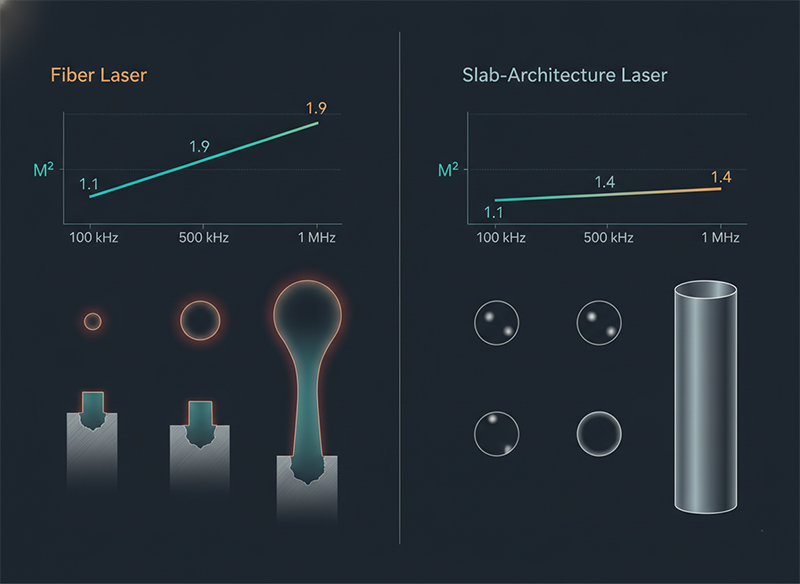
Disadvantage: Thermal control becomes critical. If beam quality (M²) drifts during a run—if the laser’s focus shifts from 1.2 to 1.6 due to thermal lensing—the process window collapses. A fiber laser holding M² at 1.2 under 100 kHz load might drift to 1.9 at 500 kHz, causing taper angle to spike from 4° to 7° and HAZ to triple. This is where slab-architecture lasers (Nd:YAG with integrated amplification, <1.4 M² consistency) outperform compact fiber systems.
When to choose: For production volumes (>10,000 parts/month). When cost-per-cycle and cost-per-good-part are primary drivers.
High repetition rate, especially in burst mode (GHz intra-burst frequency), delivers pulses so close together that material never cools between shots. Thermal accumulation becomes the ablation mechanism itself. Instead of cold ablation, you get “ablation-cooled” processing: each sub-pulse heats the thin surface layer, subsequent pulses ablate before bulk heat diffusion, creating very high material removal rates.
Advantage: Extreme throughput. A 100 µm deep via can be drilled in 2–5 microseconds instead of 200+ milliseconds. For production lines doing millions of vias, this can justify capital investment in high-power systems.
Disadvantage: Material-dependent. High repetition rate works great for copper and some ceramics (lower thermal diffusivity, heat accumulation triggers at ~0.5–4 GHz threshold). But for glass and silicon (higher thermal diffusivity, accumulation threshold at ~3–5 GHz), frequencies below 1 MHz show diminishing returns. Study of silicon vs copper in burst drilling showed copper’s ablation efficiency improved 90% going from 1 GHz to 15 GHz, while silicon showed <5% improvement beyond 3 GHz. Same laser frequency, opposite results—driven by material thermal properties.
Cost per good via: $0.10–0.18 (glass). Rework rate: 8–15% (due to thermal stress and cracking risk).
When to choose: Only when throughput economics clearly justify the risk. When your material’s thermal diffusivity is low enough to benefit (copper, some ceramics). Not recommended for glass, silicon, or high-precision work unless thermal management is bulletproof.
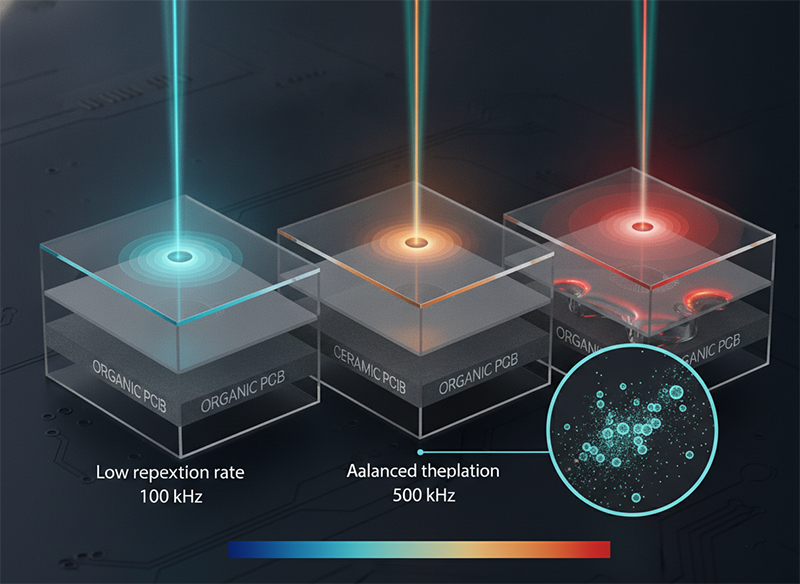
Metric | Low (100–200 kHz) | Medium (300–800 kHz) | High (1–2 MHz) HAZ depth | <5 µm | 8–15 µm | 15–30 µm (thermal stress risk) Via sidewall taper | 2–3° | 4–7° | 6–10° (risk of cracks) Cost per good via | $0.08–0.12 | $0.09–0.14 | $0.10–0.18 Rework rate | <2% | 3–8% | 8–15% Cycle time per via | 200–300 ms | 60–100 ms | 2–5 ms Throughput relative | 1× | 2.5–3× | 50–100× Best for | Precision (aerospace, medical) | Production (packaging, electronics) | Volume (if material supports it)
| Metric | Low (100–200 kHz) | Medium (300–800 kHz) | High (1–2 MHz) |
| HAZ depth | <5 µm | 8–15 µm | 15–30 µm (thermal stress risk) |
| Via sidewall taper | 2–3° | 4–7° | 6–10° (risk of cracks) |
| Cost per good via | $0.08–0.12 | $0.09–0.14 | $0.10–0.18 |
| Rework rate | <2% | 3–8% | 8–15% |
| Cycle time per via | 200–300 ms | 60–100 ms | 2–5 ms |
| Throughput relative | 1× | 2.5–3× | 50–100× |
| Best for | Precision (aerospace, medical) | Production (packaging, electronics) | Volume (if material supports it) |
Here’s the part that separates winners from rework disasters.
Fiber lasers and compact rod-based systems hold excellent M² at low repetition rates (100 kHz: M² <1.1). But as frequency climbs, thermal lensing in the gain medium causes beam quality to degrade. At 500 kHz, M² might drift to 1.4. At 1 MHz, 1.8 or higher. Each increment in M² reduces focus spot area (proportional to 1/M²) and increases divergence. In production drilling, this shows up as:
Slab-architecture ultrafast lasers (100–300W, integrated amplification with large thermal mass) maintain M² <1.4 consistency from 50 kHz to 1 MHz because the broad cooling surface and distributed gain prevent thermal lensing. This is not a marketing claim—it’s a physics constraint: the slab geometry trades peak power density for thermal stability. For production, that trade is worth it.
Ask yourself four questions:
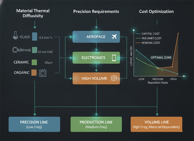
Glass (0.5 mm²/s, high), aluminum nitride ceramic (10 mm²/s, very high), organic FR-4 (0.1 mm²/s, low). Higher thermal diffusivity materials can tolerate higher repetition rates because heat dissipates faster. Glass and ceramics can often run 300–800 kHz without thermal stress. Organics need caution above 300 kHz.
Aerospace/medical parts: <5 µm HAZ, 2–4° taper, no micro-cracks. Choose low repetition rate (100–200 kHz), accept longer cycle time, eliminate rework.
Consumer electronics / standard packaging: <15 µm HAZ acceptable, 4–7° taper okay, <5% rework acceptable. Choose medium (300–800 kHz), balance speed and quality.
High-volume commodity parts (if material supports): ≤30 µm HAZ acceptable, <10% rework acceptable. High repetition rate only if copper or ceramics with proven thermal stability.
This is the question competitors avoid. If your laser is fiber-based or compact rod, M² will drift above 800 kHz—plan accordingly. If it’s slab-architecture (Laserion’s design), M² stays stable to 1+ MHz—you can push higher repetition rates safely.
Low rework (precision-focused): Capital $400K–800K. Per-part cost $0.08–0.12. Accept 2–3 minute cycle times.
Balanced (medium): Capital $800K–1.5M. Per-part cost $0.10–0.15. Accept 30–60 second cycle times.
High-volume (throughput-focused): Capital $1.5M–2.5M. Per-part cost $0.12–0.20. Require 1–5 second cycle times only if material physics supports it.
There’s a sourcing trap that catches most packaging integrators: you source glass interposers from one vendor, ceramic heatspreaders from another, organic PCB from a third. Each vendor optimizes for their material and tells you “this repetition rate is optimal for your application.” What they don’t tell you: they’ve chosen repetition rates that work for their specific laser architecture, not necessarily what’s best for your total cost of ownership.
When a thermal spike from the glass process starts causing ceramic delamination, or when organic HAZ keeps growing as you scale volumes, you’re in the middle. No vendor takes responsibility. You hire a consultant. Downtime extends. Cost compounds.
The sourcing pivot: instead of asking “which vendor is best for glass?”, ask “is this light-source architecture designed to hold M² and thermal stability as repetition rate scales?” If yes, you can run all three processes on one platform, manage supply through one relationship, and debug process interactions on unified data. That’s not vendor lock-in. That’s risk reduction.
If you’re sourcing at scale, talking to a supplier directly surfaces details no RFQ will tell you. Real M² behavior under thermal load that lab specs don’t capture. Actual cost-per-good-via from peer installations running production volume. Supply continuity during allocation crises. And whether their engineering team has actually debugged the integration problem you’re facing—not just optimized one material in isolation.
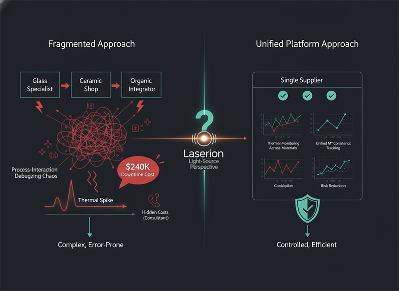
Advanced packaging stacks three materials—glass, ceramic, organic—into integrated systems where one process’s thermal byproduct becomes the next material’s constraint. That’s not a problem you solve with three separate specialists each optimizing for their material. It’s a system-level challenge that only a light-source perspective reveals: quality at scale depends on whether your ultrafast laser can hold beam quality (low M²) while adjusting repetition rate to match each material’s thermal properties.
That’s why we built slab-architecture sources that reach 200–300 watts while keeping M² under 1.4 across the full repetition rate spectrum. Not for the peak power. For the stability. The margin. The ability to run process windows tight enough across all three materials without re-qualifying the entire integration. In advanced packaging, that light-source architecture is the asset. The equipment and motion control are just the means to use it.
Q: Why doesn’t higher repetition rate always mean faster drilling?
A: Higher repetition rate increases pulse density but also cumulative thermal load. If that heat accumulation exceeds the material’s thermal diffusivity (how fast it cools), you shift from cold ablation to heat-driven vaporization, triggering thermal damage, cracks, and HAZ growth. For materials like glass with high thermal diffusivity, going above 500 kHz shows diminishing returns. For materials like copper with low thermal diffusivity, high repetition rate (>1 MHz) actually improves efficiency because thermal saturation mode becomes the primary ablation mechanism.
Q: What’s the typical HAZ depth at different repetition rates?
A: Low repetition rate (100–200 kHz): <5 µm. Medium (300–800 kHz): 8–15 µm. High (1–2 MHz): 15–30 µm. On organic PCB, each 5 µm increase in HAZ roughly doubles delamination risk after thermal cycling. On glass and ceramics, HAZ directly correlates with crack initiation risk.
Q: How does beam quality (M²) affect the choice of repetition rate?
A: M² directly determines achievable focus spot size (proportional to 1/M²) and depth of focus. At a given spot size, low M² means higher peak intensity and better precision. As repetition rate climbs, thermal lensing in the laser’s gain medium causes M² to degrade (especially in fiber systems). If M² drifts from 1.2 to 1.8 during a production run, your spot area increases ~2.25×, and focus depth shrinks, causing via sidewall taper to change mid-drill. Slab-architecture lasers hold M² stable, letting you confidently use higher repetition rates.
Q: Can I use the same repetition rate for glass, ceramic, and organic substrates?
A: Not optimally. Glass and ceramic have high thermal diffusivity (heat dissipates fast), so they tolerate 300–800 kHz without thermal damage. Organic FR-4 has low thermal diffusivity (heat builds up), requiring caution above 300 kHz. If you run a fixed 500 kHz across all three stacked in one panel, organic layers risk deep HAZ and delamination. Best practice: run 200–300 kHz for organic processing in integrated stacks, and compensate for glass/ceramic speed loss by increasing average power or using burst mode with controlled intra-burst frequency.
Q: What’s the cost impact of choosing the wrong repetition rate?
A: Significant. If you choose 1 MHz for glass vias expecting speed, but thermal accumulation causes 47% rejection and HAZ-driven delamination, your cost-per-good-via jumps from $0.10 to $0.25+ (including rework). Over a year processing 10M vias, that’s $1.5M in extra cost. Switching to 200–300 kHz drops rejection to <2%, cost-per-good-via to $0.08–0.10, and amortizes the slower cycle time via higher yield and zero rework.
Q: How do I know if my laser’s M² is stable at my chosen repetition rate?
A: Install a beam-profiler diagnostic every 2–4 hours during production runs at your target repetition rate. Measure beam waist size, divergence angle, and calculate M². If M² climbs more than 0.1–0.15 units over an 8-hour shift, you have thermal lensing or alignment drift. Slab-architecture sources should hold M² within ±0.05 units. Fiber systems above 800 kHz often show M² drift of 0.2+ units, signaling process risk.
Q: Should I always choose the lowest repetition rate for best quality?
A: No. Lowest repetition rate gives best surface finish but worst throughput and cycle time cost. Medium repetition rate (300–800 kHz for glass/ceramic, 100–300 kHz for organics) is usually optimal: good HAZ control, reasonable taper angle, and 2–3× throughput improvement over low frequency. Choose low repetition rate only when quality critical outweighs cost (aerospace, medical implants). Choose high only when material physics supports it (copper, thermally-stable ceramics) and your laser architecture holds M².