
A glass part can pass dimensional inspection and still be a reject. The shape is right, the corners are crisp, and then it snaps in a bend test — at the corner, never the straight edge. We have watched teams chase the motion system for that failure when the answer was in the laser source.
“We treated complex-shape cutting as a motion problem — if the stage could trace the R-corners and the inner cutout, the part was done. Dimensionally the contours were fine, then the parts failed four-point bend tests at the corners, not the straights. The filament that cut a clean straight edge thinned through the tight radius, where pulse overlap crowds and any beam-quality drift shows up first. On a closed contour the corner is where stress concentrates and where a crack starts. What set the part’s fracture strength wasn’t whether the machine could follow the shape — every machine could. It was whether the source held the filament uniform through the turn. We had optimized the gantry and ignored the beam.” — process engineer, complex cover-glass contour qualification
That is the gap this article addresses. Cutting complex glass shapes with ultrafast lasers is no longer about tracing a contour. It is about keeping the cut strong where the contour turns.
Ultrafast lasers cut complex glass shapes by forming a filament — a self-guided channel of modification — inside the glass, then separating along it. A tightly focused femtosecond or picosecond pulse drives nonlinear absorption; Kerr self-focusing and plasma defocusing balance into a long, thin filament, or a Bessel beam produces one directly. Scanning that filament along the contour writes the break path. Because it is non-contact and nearly heat-free, the edge stays strong — provided the filament stays uniform through corners and inner radii.
People search this when a product moves from straight or rectangular cuts to real shapes: rounded corners, camera and sensor cutouts, inner slots, and chamfered edges on cover glass, automotive displays, AR waveguides, and microfluidic parts. The machine demos look clean, so the assumption is that shape capability is the whole question.
In our experience supporting glass cutting lines, shape capability is rarely where parts fail. Nearly every modern system can trace a complex contour. Parts fail in service, and they fail at the features the contour added — the tight radius, the inner corner, the chamfer — because that is where stress concentrates and where any weakness in the cut becomes a crack.
So this guide goes past “can the laser make the shape.” It explains how the filament forms, why corners and inner contours decide edge strength, why the laser source rather than the gantry sets that strength, how bevels can be cut in a single pass, and what it takes to hold quality at speed on thick parts. Each section maps to a decision an engineer or buyer is making when a complex-shape glass part moves toward production.
To judge a complex-shape process, it helps to know what is doing the cutting. Glass is transparent at the usual 1 µm wavelength, so the energy only couples in where intensity is high enough for nonlinear absorption.
Two related mechanisms create the long, thin modification a clean separation needs. In filamentation, the Kerr effect makes the beam self-focus until it ionizes the glass; the resulting plasma defocuses it; the two effects balance and repeat along the path, forming a filament that can extend several millimeters. Tubular and filamentary processing in transparent media works on exactly this dynamic balance.
A Bessel beam reaches the same goal by design. Formed by a conical superposition of plane waves, its central hotspot stays tight over a long focal range, so it writes a high-aspect-ratio modification in a single shot. Published work has cut 700 µm glass in a single pass at up to 270 mm/s with picosecond Bessel beams, and the elliptical channel they form defines a stress plane that guides a clean cleave.
The practical point for complex shapes: both mechanisms depend on a tight focus held over depth, and both are sensitive to beam quality. That sensitivity is what corners expose.
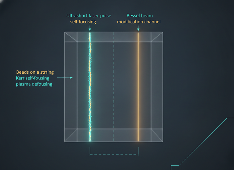
On a straight edge, the filament sees steady conditions: constant direction, even pulse spacing, consistent focus. A corner breaks all three at once.
At a tight radius the scan slows and turns, so pulse overlap crowds on the inside of the curve and stretches on the outside. Any drift in pulse energy or beam quality, invisible on a straight, shows up here as a thinning or wandering filament. And a closed contour concentrates mechanical stress precisely at these corners and inner features.
Put those together and the corner becomes the crack-initiation site. Subsurface microcracks and modification from any cutting process reduce the edge strength of brittle glass, and the corner is where they matter most because that is where the part bends and impacts in service. A part can look perfect and still carry a weak corner that fails a four-point bend test.
This is why edge strength, measured at the corners and inner contour, is the metric that actually qualifies a complex-shape process — not contour accuracy alone.
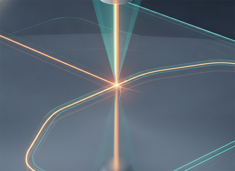
If corner edge strength is the real metric, the next question is what controls it. Most comparisons focus on the gantry, the enclosure, and the software. The deciding variable sits earlier in the chain.
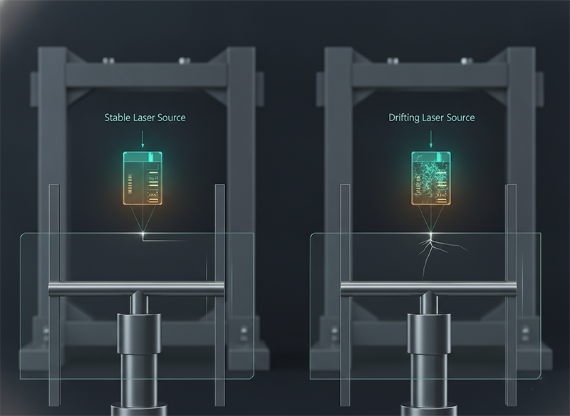
“Two systems, both demoed clean complex cuts — rounded corners, inner cutouts, the works. On the shape, they were equal. The deciding number wasn’t shape capability; it was four-point-bend edge strength after cutting, measured at the corners and the inner contour. One held edge strength close to the straight-edge value; the other dropped sharply where the contour turned, because its laser source drifted in pulse energy and beam quality and the filament thinned through the radius. Both machines ‘cut complex shapes.’ Only one kept the part strong where it bends in service. We had been comparing motion systems and enclosures — the variable that mattered lived in the laser source.” — R&D lead, glass cutting line dual-vendor evaluation
A filament is only as uniform as the beam that forms it. Pulse-energy stability and beam quality decide whether the modification stays consistent through a turn, and therefore whether the corner keeps its strength. The motion system can trace any shape; it cannot fix a filament that thinned because the source drifted. This is the case for evaluating a complex-shape process at the source level, not only the machine level.
Here is how the common approaches compare for complex shapes specifically:
| Aspect | Mechanical scribe-and-break | CO₂ thermal | Ultrafast filament / Bessel |
|---|---|---|---|
| Tight radii / inner contours | Limited, multiple tools | Limited | Software-defined, free-form |
| Heat-affected zone | None, but high mechanical stress | Large | Very small |
| Corner edge strength | Low, chip-prone | Medium | High, if filament stays uniform |
| Bevels / chamfers | Separate grinding step | Separate step | Possible in one pass with beam shaping |
| What limits it | Tooling and geometry | Thermal cracking | Beam quality and stability of the source |
Complex parts often need more than an outline. A safe, durable glass edge is usually chamfered, and traditionally that means a separate mechanical grinding step after cutting.
Beam shaping is changing that. By splitting the focus into coordinated foci across both the plane and the depth, a shaped beam can form a C-chamfer or trapezoidal profile and cut the main contour and its bevels in a single pass. Research on ultrafast laser–modified C-shaped edges shows tailored geometries can improve mechanical behavior against impacts and defects, which is the real reason a bevel exists.
For a complex-shape line, this matters twice over: it removes a grinding step, and it puts the edge profile under the same process that controls edge strength — so the corner and its chamfer are formed together rather than fought over in post-processing.
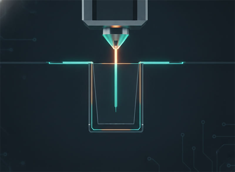
Thin straight cuts are forgiving. Thick parts with tight inner contours, run at production speed, are where the source is tested.
“We specified the highest-power picosecond machine for thick, large complex parts — more power, more speed, the safe call. On thin straight cuts it flew. On thick parts with tight inner contours, the filament wouldn’t stay uniform through depth and radius at the speed we’d bought the power for; corner edge strength fell and we throttled back, losing the throughput we’d paid for. The limit wasn’t watts — it was holding beam quality at power so the filament stayed uniform through the turn. A source that keeps M² low at 100–300 W cut the same contours at speed with corner strength intact.” — process integrator, thick complex-glass line scale-up
Focusable intensity scales with power over M² squared, so a high-power source that loses beam quality cannot form a tight, uniform filament through a corner no matter how many watts it carries. Holding low M² as average power rises is an architecture problem. Slab integrated amplification is built for this balance — published Innoslab work held M² under 1.4 at 280 W — which is what lets a complex-shape line keep corner edge strength while running thick parts at speed.
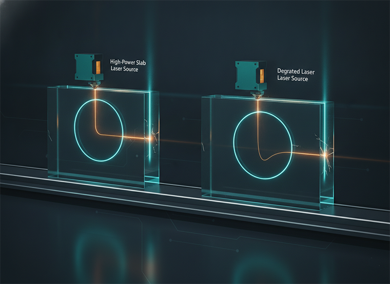
Use this to evaluate a complex-shape process without getting anchored on the machine. If your part has tight radii, inner cutouts, or chamfers, qualify it on four-point-bend edge strength measured at the corners and inner contour, not on contour accuracy alone. If two systems both cut the shape, compare the laser source — pulse-energy stability and beam quality — because that is what holds the filament through a turn. If you need a beveled edge, ask whether it can be formed in the same pass through beam shaping rather than added by grinding. And if you run thick or large parts at volume, check that the source keeps M² low at your operating power, since that is what lets the filament stay uniform at speed. When the part is a simple straight cut, these distinctions matter less; they decide everything once the contour turns.
Two checks separate a real complex-shape process from a clean demo. First, ask for edge-strength data — four-point bending — measured at the corners and inner contours of your geometry, not on a straight coupon. Second, ask what laser source forms the cut and how its beam quality and pulse stability hold up at your power and speed, because that is where corner strength lives. If you are sourcing at scale, talking to a supplier directly can surface details no product listing will tell you — how the filament behaves through your tightest radius, and whether the edge will survive where your product actually bends.
The part that passed inspection and failed the bend test makes the point better than any spec sheet: with complex glass shapes, the question is never whether the laser can trace the outline. It is whether the cut stays strong where the outline turns. Corners and inner contours are where stress gathers and where a weak filament becomes a crack — and the filament is only as good as the source that forms it. Specify the edge strength at the corner, and you are specifying the laser, not the gantry.
How do ultrafast lasers cut complex shapes in glass? They form a filament — a long, thin zone of modification inside the glass — using nonlinear absorption, then separate along it. A femtosecond or picosecond pulse self-focuses through the Kerr effect, balanced by plasma defocusing, or a Bessel beam writes the channel directly. Scanning the filament along any contour, including curves and inner cutouts, defines the break path.
Why do complex glass parts crack at the corners? A closed contour concentrates mechanical stress at corners and inner features, and a tight radius also crowds pulse overlap, where any beam-quality drift thins the filament. Together that makes the corner the most likely crack-initiation site, which is why parts often fail bend tests there rather than on the straight edges.
Can ultrafast lasers cut inner cutouts and holes, not just outlines? Yes. Because the cut is software-defined and non-contact, inner contours, slots, and holes are cut the same way as outer contours. The limit is not geometry but holding filament uniformity through tight inner radii, which depends on the laser source.
Can a bevel or chamfer be cut with the laser instead of ground? Increasingly, yes. By shaping the beam into coordinated foci across the plane and depth, a C-chamfer or trapezoidal edge can be formed in the same pass as the main cut, removing a separate grinding step and keeping the edge profile under the same process that controls edge strength.
What decides edge strength in complex-shape cutting — the machine or the laser? The laser source. Most machines can trace the shape; what holds corner edge strength is the filament’s uniformity, set by the source’s pulse-energy stability and beam quality. A drifting source thins the filament through turns regardless of how good the motion system is.
Does higher laser power give cleaner complex cuts? Not by itself. Focusable intensity scales as power over M² squared, so power that comes with degraded beam quality cannot form a tight filament through a corner. Holding low M² at high power — an architecture question — is what lets thick parts be cut at speed with corner strength intact.
How should I qualify a complex-shape glass process? Measure four-point-bend edge strength at the corners and inner contours of your actual geometry, not on a straight coupon. Compare the laser source’s beam quality and stability between systems, and confirm the result holds at your production speed and glass thickness.
Which glass types and thicknesses suit ultrafast complex-shape cutting? Soda-lime, borosilicate, aluminosilicate (strengthened cover glass), and fused silica are all processed this way, from ultra-thin cover glass to thicker parts. Thicker and strengthened glass demands more from filament uniformity and source beam quality, so qualify the process on your specific material.