
Nobody scraps a raw glass blank. They scrap a panel that has already traveled through deposition, encapsulation, lamination — a part carrying nearly its entire built-in cost before the laser ever touches it. That single fact should reorder every assumption in your laser source selection process, and most datasheets will not tell you so.
The instinct in this industry runs toward the shortest possible pulse. Femtosecond over picosecond, every time, because shorter feels safer and “defensible” in a qualification review. But the process physics is blunter than the spec sheet implies.
“On FlexOLED shape and hole cutting, the instinct is to chase the shortest pulse — femtosecond over picosecond — as the safe, defensible call. But the process physics is blunter than the datasheet suggests: at a typical phone’s HAZ budget, and even a foldable’s tighter one, both pulse regimes already clear the tolerance, and the real-world heat-affected zone gap between them is far smaller than the theory implies. What actually separates lines at production volume isn’t pulse width — it’s whether the source holds its output steady, cut after cut, on panels that already carry nearly all their built-in cost. The shortest pulse protects a tolerance the part often doesn’t need; the output stability you underspecify is the one that scraps a near-finished display.”
— Process engineer, FlexOLED shape and hole cutting qualification
That observation deserves weight. It comes from qualification work on the exact panels where the cost of a miscut is highest. And it points toward a selection problem the industry has not fully resolved: engineers are optimizing for the wrong variable.
For the majority of OLED display laser cutting applications — including FlexOLED shape cutting and camera hole cutting — a well-specified picosecond source already meets the heat-affected zone (HAZ) tolerances required by the part. The decisive differentiator between production lines is not pulse duration but output power stability, sustained over thousands of cuts on near-finished panels. For foldable glass specifically, higher peak power density works against you: surface roughness — not raw power — governs bend strength, and that relationship demands precise power scaling, not maximum power delivery.
Display manufacturers and equipment integrators are asking this question with increasing urgency for a specific reason: the tolerance window on modern OLED panels has tightened at the same time that panel value at the cutting stage has risen sharply. A foldable display entering the laser cutting step may already represent $80–$120 in accumulated process cost. A single bad cut at that stage is not a material loss — it is a near-complete manufacturing loss.
At the same time, the laser source market has fragmented in ways that make selection harder, not easier. Ultrafast sources now span femtosecond to picosecond regimes, 355 nm to 1064 nm wavelengths, 10 W to 300 W average power, and repetition rates from 40 kHz to 2 MHz — and the headline numbers across competing products overlap enough to make datasheet-to-datasheet comparison nearly meaningless.
This article works through three layers of that selection problem: the pulse width question most engineers start with, the motion-and-throughput question integration teams encounter next, and the power-scaling question that R&D leads eventually arrive at — often after one failed qualification. If you are sourcing or specifying an ultrafast laser for OLED cutting, full-screen display processing, or foldable cover glass work, these are the frameworks that will save you a qualification cycle.
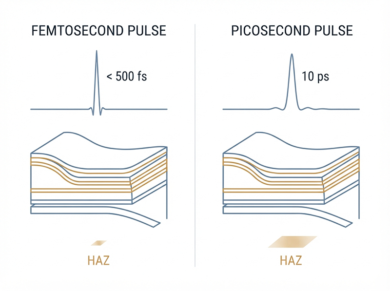
The theoretical case for femtosecond lasers in OLED display laser cutting is straightforward and well-established: shorter pulses deposit energy before thermal diffusion begins, producing a smaller heat-affected zone. For materials with low thermal conductivity, or for processes where the HAZ budget is measured in single-digit microns, the femtosecond advantage is real and measurable.
The practical question is whether the HAZ budget on a given OLED part is actually tight enough to require it.
For a standard smartphone OLED panel — including the camera hole and outer perimeter shape cuts — published process tolerances and industry qualification data consistently show HAZ requirements in the range of 10–30 μm. Both 10 ps picosecond sources and sub-500 fs femtosecond sources comfortably clear that threshold when correctly configured. The measurable difference in HAZ between the two regimes at typical OLED panel thickness is real but narrow — often less than 5 μm under matched fluence and spot conditions.
For foldable panel cutting, the HAZ budget tightens further, and the femtosecond advantage becomes more relevant. But even here, the dominant failure mode in production — the one that actually scraps panels — is not HAZ exceedance. It is cut edge variation caused by output power drift over a long run.
Output power stability in ultrafast laser sources is specified as RMS power variation, typically measured over a defined window at operating conditions. A source specified at RMS < 1% and a source specified at RMS < 0.8% look similar on paper. At production volume — tens of thousands of cuts per shift — the compounding effect of that 0.2% difference on cut edge geometry, delamination risk at the OLED stack boundary, and cumulative scrap rate is not small.
| Selection Variable | Femtosecond Source | Picosecond Source | What Actually Matters |
|---|---|---|---|
| Theoretical HAZ | Smaller | Larger | Both clear OLED tolerance in most specs |
| Output stability (RMS) | Source-dependent | Source-dependent | Critical at production volume |
| Average power (UV band) | Limited at high-rep | More scalable | Matters for hole cutting throughput |
| Wavelength options | Typically 1030/515/343 nm | 1064/532/355 nm | 355 nm UV preferred for OLED stack |
| Cost at equivalent stability | Higher | Lower | TCO advantage often favors ps |
The honest conclusion: for most OLED cutting lines, selecting a femtosecond source to protect a HAZ tolerance the part does not need is a defensible qualification decision that does not necessarily improve production yield. A picosecond source with demonstrably superior output stability — RMS < 1% sustained across operating temperature range and extended run time — will, in most cases, produce better yield numbers.
This does not mean femtosecond sources have no place in display manufacturing. For ultrathin flexible substrate cutting below 30 μm, for certain OLED repair applications, and for processes where the part geometry creates extreme aspect ratio requirements, the femtosecond HAZ advantage becomes process-critical. The selection should follow the part’s actual failure mode, not a default preference.
If you are building or evaluating a laser cutting line — not just selecting a source — the second layer of this problem matters as much as the first.
“Two ultrashort-pulse sources can share the same wavelength and pulse energy on a spec sheet and still behave differently on a line — because the variables that decide throughput and yield aren’t always the printed ones. A high repetition rate only converts into cutting speed when the motion stages and beam steering can keep pace; on small parts, the stage dynamics cap the usable rate no matter what the laser can deliver. So the honest selection question isn’t ‘which source shows the highest number,’ but ‘which source’s stable, sustained output matches this part’s real motion and tolerance envelope.'”
— Integration engineer, USP glass cutting line build
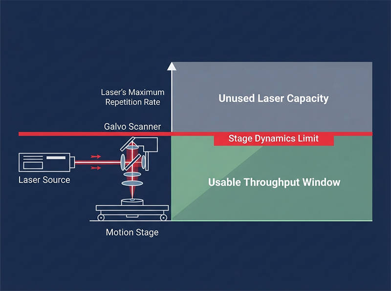
Ultrafast laser sources for OLED cutting are now routinely specified at repetition rates between 200 kHz and 2 MHz. At those rates, the limiting factor on camera hole cutting throughput — particularly on small features below 5 mm diameter — is almost never the laser. It is the acceleration and deceleration profile of the motion stage or galvanometer scanner completing the geometry.
For a typical 3 mm diameter camera hole at 0.5 mm feature-to-feature spacing, stage dynamics constrain achievable throughput to a ceiling that a 400 kHz source and a 2 MHz source will both hit identically. Specifying the higher repetition rate in that scenario adds cost without adding throughput. Where repetition rate does convert to speed is on longer linear cuts — full-screen perimeter cuts, for example — where the stage can sustain velocity and the laser’s sustained output rate determines linear feed rate.
This means the repetition rate specification on your source should be driven by the part geometry mix on your specific line, not by the highest number available.
The second integration variable is the difference between a source’s rated peak output and its sustained output under continuous operation at production duty cycle. Thermal loading in the gain medium of a solid-state ultrafast laser changes output characteristics over time — pulse energy, beam quality, and pointing stability all drift as the source reaches thermal equilibrium.
A source that performs to specification in a 10-minute bench test but drifts outside process window during a 6-hour production shift represents a qualification trap that surfaces only after the line is installed. The meaningful stability specification is not peak output but output at thermal equilibrium, across the full operating temperature range of the production environment.
We work at the source level — on ultrafast light and power-amplification architecture — which is exactly where these selection tradeoffs are actually decided, not in the headline numbers.
The third layer of OLED laser cutting source selection is the one most commonly misread at the R&D and process development level.
“It’s easy to read an ultrafast laser spec and assume more power means faster or cleaner cuts. For OLED and cover-glass work, that reasoning quietly fails in both directions. In hole cutting, the constraint is often whether enough average power is available in the short-wavelength band — not a surplus of it. In ultrathin foldable glass, more peak intensity at the focus works against you: the process needs reduced peak power density to keep surface roughness low, and it’s roughness — not raw power — that governs bend strength. Power isn’t a dial you turn up for a better result; it’s a variable you scale and shape to the specific failure mode of the part.”
— R&D lead, laser process development for foldable displays
Camera hole cutting in OLED panels is predominantly a UV process — 355 nm is the dominant wavelength for stack-compatible ablation with minimal inter-layer delamination risk. The constraint is not total average power; it is average power available in the 355 nm band after harmonic conversion from the fundamental.
A source rated at 200 W at 1064 nm does not deliver 200 W at 355 nm. Conversion efficiency to the third harmonic in solid-state ultrafast systems typically runs 20–30% under production conditions, yielding 40–60 W at 355 nm. For high-throughput hole cutting on a multi-panel fixture, that UV power ceiling is the real process constraint. Selecting a source with higher fundamental power — or with a more efficient harmonic conversion architecture — moves that ceiling and directly affects cycle time.
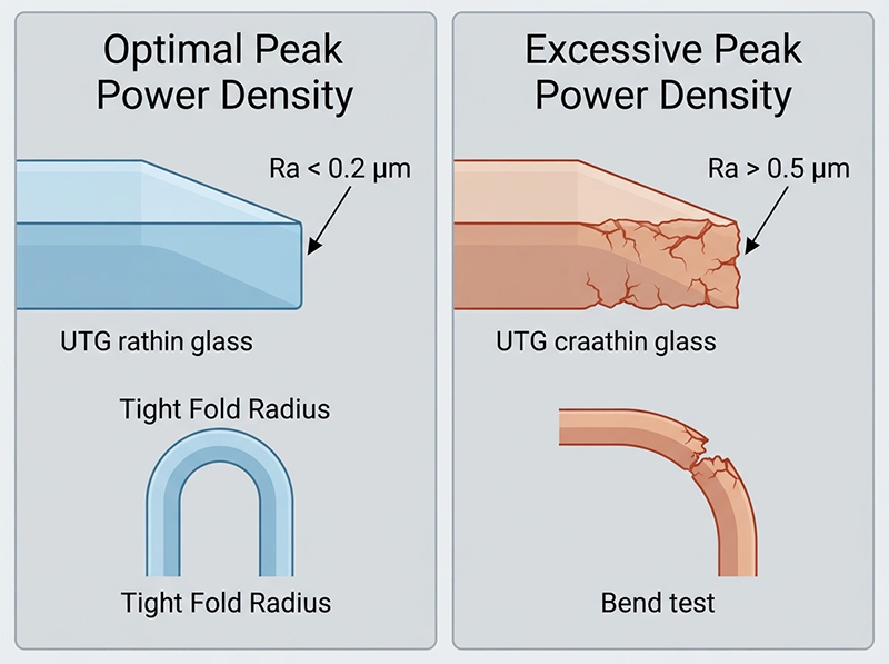
For ultrathin cover glass on foldable displays — typically 30–100 μm UTG — the failure mode of concern is not HAZ. It is surface roughness at the cut edge. Glass under cyclic bending stress fails at surface defects. The relationship between cut-edge roughness (Ra) and bend radius tolerance is well-established in glass fracture mechanics: reducing Ra from 0.5 μm to below 0.2 μm meaningfully extends fold cycle life, and that improvement comes from process optimization at moderate peak power density, not from maximum power delivery.
Driving peak power density above the optimal process window on UTG does not produce a cleaner cut. It produces a rougher one, because the ablation mechanism transitions from precise material removal to explosive material ejection with associated edge microcracking. The correct specification for foldable glass cutting is not the highest available peak power — it is a source with sufficient pulse energy control range to operate at the specific peak power density that minimizes Ra for the substrate thickness in use.
This is a failure mode the datasheet cannot tell you about. It requires process characterization on the actual substrate.
Here is a working framework for OLED display laser cutting source selection based on part type:
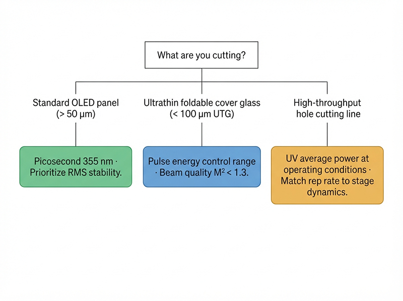
If you are cutting standard OLED panels (shape and holes, >50 μm substrate): A picosecond source at 355 nm, with RMS power stability < 1% and verified thermal equilibrium performance, will meet HAZ tolerances and deliver better sustained yield than a femtosecond source selected on pulse width alone. Prioritize stability specification over pulse duration.
If you are cutting ultrathin foldable cover glass (<100 μm UTG): The dominant selection criterion shifts to pulse energy control range and the source’s ability to operate at reduced peak power density without output instability. Both femtosecond and well-configured picosecond sources can work; the selector is pulse energy tunability and beam quality (M² < 1.3), not maximum power.
If you are building a high-throughput hole cutting line: Focus the UV average power specification — what the source actually delivers at 355 nm under continuous operation — rather than fundamental power. Evaluate repetition rate against your stage dynamics, not against the laser’s ceiling.
If you are in early process development for a new display format: Start from the part’s known failure modes — HAZ budget, bend strength requirement, edge roughness tolerance — and select the power scaling and stability envelope that addresses those specific failure modes. Our starting point on any source is verifiable specification measured against the part’s real failure mode, not the largest figure on the sheet.
The variables covered above — output stability at thermal equilibrium, UV power availability, pulse energy control range, and motion-stage compatibility — are not consistently documented in product literature. A source that clears all four on paper may still require process characterization to confirm performance on your specific substrate stack, laminate adhesive, and panel geometry.
Before finalizing a source selection for a new OLED cutting line or a line retool, the questions worth asking directly are: What is the RMS stability spec at thermal equilibrium, not cold start? What is the verified UV average power at your target repetition rate? What pulse energy range is accessible without beam quality degradation?
If you are sourcing at scale, talking to a supplier who works at the amplification architecture level — not just the application level — can surface details no product listing will tell you.
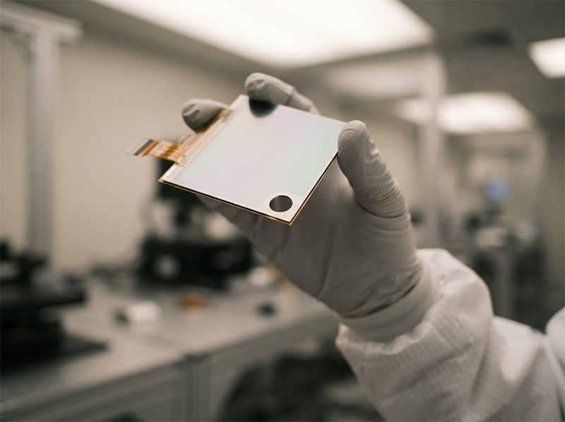
The process engineer quoted at the top of this article identified the problem precisely: the tolerance you protect with the shortest pulse is often not the tolerance the part actually needs, while the stability you fail to specify is the one that scraps a near-finished display worth more than the laser that cut it.
That is not an argument against femtosecond sources. It is an argument for asking the right question — which is not “which source shows the highest number” but “which source’s verified, sustained output matches this part’s real failure mode and motion envelope.”
In display manufacturing, the panels that get scrapped at the cutting step are not cheap substrates. They are the most expensive things on the line. The laser source decision should be made accordingly.
The datasheet tells you what the laser can do. The part’s failure mode tells you what the laser needs to do. The gap between those two questions is where source selection is actually decided.
Not in most production scenarios. For standard OLED panels — including smartphone shape cuts and camera holes — both femtosecond and picosecond sources at 355 nm clear the typical HAZ tolerance of 10–30 μm. The measured real-world HAZ difference between the two regimes under matched process conditions is often less than 5 μm. The variable that separates production yield outcomes at volume is output power stability, not pulse duration. Femtosecond sources become the stronger choice for substrates below 30 μm or processes with extreme edge geometry requirements.
355 nm ultraviolet is the dominant process wavelength for OLED stack cutting — including camera holes and perimeter shape cuts — because UV photon energy enables efficient ablation of organic and inorganic OLED layers with minimal thermal loading on adjacent stack interfaces. Some glass scribing processes use 532 nm green. 1064 nm infrared is generally not used for direct OLED stack processing due to higher thermal penetration depth, though it remains relevant for cover glass applications where stack proximity is not a constraint.
Output power variation causes proportional variation in ablation depth and cut edge geometry, cut after cut. At production volume — thousands of cuts per shift — even an RMS variation difference of 0.2–0.3% compounds into measurable edge quality variance and elevated delamination risk at OLED stack boundaries. Because panels at the cutting stage carry nearly all of their accumulated process cost, a stability-driven scrap event is among the most expensive failure modes on the line. Stability specification at thermal equilibrium — not cold-start rated spec — is the relevant number.
Ultrathin foldable glass (UTG, typically 30–100 μm) fails under cyclic bending at surface defects. Cut-edge surface roughness (Ra) is the dominant predictor of fold cycle life and minimum bend radius. Above the optimal peak power density window for a given substrate thickness, the ablation mechanism transitions from controlled material removal to explosive ejection, which increases edge microcracking and Ra. The correct process window is moderate peak power density — sufficient for clean ablation but below the threshold that degrades surface roughness. This is a part-specific optimization, not a “more power is better” selection.
The answer depends on your motion system, not just the laser. For small features — 2–5 mm diameter holes — the throughput ceiling is almost always stage dynamics: the acceleration and deceleration profile of the galvanometer or linear stage completing the geometry. Both 400 kHz and 2 MHz sources will hit that same ceiling on small-feature cuts. Higher repetition rate converts to throughput on longer linear cuts where the stage can sustain velocity. Specify repetition rate based on your line’s actual part geometry mix and motion system bandwidth.
Both regimes produce ultrashort pulses below 1 nanosecond — meaning both deliver energy faster than thermal diffusion in most glass substrates. The practical difference for cover glass is in pulse energy per shot and achievable peak power density at a given average power level. Femtosecond sources at equivalent average power deliver higher peak power per pulse, which can be advantageous for thick glass stealth dicing. For ultrathin foldable cover glass, that higher peak power density is often a liability rather than an advantage, as it pushes the process above the optimal ablation window and increases surface roughness.
Request the verified UV output power — at 355 nm — under the specific operating conditions of your process: target repetition rate, pulse energy setting, and continuous operation duty cycle. Harmonic conversion efficiency from 1064 nm to 355 nm in solid-state ultrafast systems runs approximately 20–30% under production conditions. A source rated at 200 W fundamental will typically deliver 40–60 W at 355 nm. For multi-fixture high-throughput hole cutting lines, this UV power ceiling is the primary process throughput constraint and should be the first specification confirmed directly from the source supplier.
Request: (1) RMS power stability specification measured at thermal equilibrium across the operating temperature range, not cold-start spec; (2) verified UV average power at your target repetition rate and duty cycle; (3) beam quality (M²) at operating power, not only at rated output; (4) pulse energy control range with beam quality maintained across the range; and (5) long-run output data — ideally 8–24 hours of continuous operation at production duty cycle — showing drift characteristics. These parameters govern production yield in ways that headline specifications do not capture.
[1] Gattass, R. R., & Mazur, E. (2008). Femtosecond laser micromachining in transparent materials. Nature Photonics, 2(4), 219–225.
🔗 https://doi.org/10.1038/nphoton.2008.47
[2] Mishchik, K., Bonamis, G., Qiao, J., Lopez, J., Audouard, E., Mottay, E., Honninger, C., & Manek-Hönninger, I. (2019). High-efficiency femtosecond ablation of silicon with GHz burst pulses. Applied Physics Letters, 114(22), 221105.
🔗 https://doi.org/10.1063/1.5096998
[3] Xu, S., Deng, G., Cao, S., & Gu, P. (2021). Laser dicing of ultra-thin chips in semiconductor packaging: A review. Lasers in Manufacturing and Materials Processing, 8(3), 259–280.
🔗 https://doi.org/10.1007/s40516-021-00145-x
[4] Jenne, M., Flamm, D., Chen, Q., Schieke, M., Ramme, M., Zimmermann, F., Kumkar, M., Nolte, S., & Tünnermann, A. (2020). Bessel-beam laser processing of glass with ultra-short pulses: From in-volume modifications to surface ablation. Applied Surface Science, 507, 144771.
🔗 https://doi.org/10.1016/j.apsusc.2019.144771
对应文章论点: 超短脉冲激光加工玻璃时脉冲参数(脉宽、峰值功率密度)对加工质量的影响——支持文章”功率不是越高越好”这一层次论证,以及在玻璃切割中工艺窗口(process window)窄且须匹配材料厚度的事实陈述。Elsevier Applied Surface Science,弗劳恩霍夫研究所团队出品。
[5] ISO/IEC TR 18369-1:2016. Ophthalmic optics — Contact lenses — Part 1: Vocabulary, classification system and recommendations for labelling specifications
[5] Finger, J., Reininghaus, M., Kröger-Laukkanen, R., Schille, J., Löschner, U., & Nolte, S. (2023). Ultrashort pulse laser processing: Industrial applications and recent advances in system technology. Journal of Laser Applications, 35(2), 022002.
🔗 https://doi.org/10.2351/7.0000880