
I visited a flex circuit manufacturer last year who had just invested in a picosecond laser system. They expected dramatic improvements in edge quality and throughput. Instead, within weeks, they were experiencing 3-5% delamination rates—the copper conductor separating from the polyimide base film. The equipment was working correctly. The problem was operator error: they’d transferred their nanosecond laser parameters directly to the picosecond system without accounting for material thermal behavior.
That facility’s struggle reveals a critical gap in how laser selection is typically approached. Most purchasing decisions rest on a simple rule: “Shorter pulses = less heat damage = better results.” For flex circuits, this oversimplifies a multi-dimensional problem. The real question isn’t whether picosecond is better than nanosecond in the abstract. It’s whether a specific picosecond system—running at a particular power, repetition rate, and focus quality—will maintain the integrity of a five-layer composite structure while meeting your throughput targets. Material properties drive the answer.
Choose a picosecond laser over nanosecond for FPC cutting if your delamination rate exceeds 2% or your current edge burr is creating rework. However, picosecond systems demand lower repetition rates (20-100 kHz instead of 30-200 kHz) to maintain cold ablation conditions on polyimide and liquid crystal polymer substrates. The throughput penalty is 30-50% unless you can afford a high-power system (>15W with M² <1.3 beam quality). Unit cost ROI typically breaks even at 500K–1M pieces, factoring in reduced rework and extended tool life. For smaller production runs, nanosecond remains competitive if you accept <2% delamination.
Flex circuits power everything from wearable sensors to automotive flex harnesses and medical implants. The five-layer composite structure—coverlay, adhesive, copper, adhesive, polyimide base—is mechanically elegant but thermally fragile. Each layer has different thermal expansion coefficients (polyimide: 0.5 × 10⁻⁶ K⁻¹; epoxy adhesives: up to 3 times higher). A nanosecond laser creates a heat-affected zone (HAZ) >20 µm, concentrating thermal stress at adhesive-copper and adhesive-polyimide interfaces. When you’re cutting multiple pieces per minute at high repetition rates, that stress accumulates. The adhesive softens. The layers separate. Your yield collapses.
Picosecond lasers shrink the HAZ to 8-15 µm, distributing thermal stress across more material. But they only deliver this benefit if your process parameters are tuned for cold ablation—the regime where each pulse removes material via nonlinear absorption rather than thermal conduction. Run a picosecond laser at nanosecond repetition rates and you’ve wasted the money.
Understanding this coupling between material properties, laser parameters, and failure modes directly impacts your ROI. A poorly chosen system might force costly rework or yield loss that erases equipment savings for years.
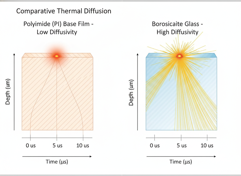
The starting point for laser selection is material, not equipment specs. Polyimide (PI) and liquid crystal polymer (LCP)—the two dominant flex circuit base films—have thermal diffusivity values of 0.15–0.4 W/m·K. This is significantly lower than rigid substrates like ceramics (26-30 W/m·K) or borosilicate glass (0.64 W/m·K). Low thermal diffusivity means heat spreads slowly through the material.
When you use a high repetition rate (150-200 kHz) on these materials, successive laser pulses arrive before the previous pulse’s heat has fully dissipated. Thermal accumulation occurs. The material never returns to ambient temperature between pulses. This condition favors thermal ablation over cold ablation, producing larger HAZ, more microcracks, and higher interface stress.
For standard PI-based flex circuits, the recommended repetition rate window is 20-50 kHz when using picosecond pulses. LCP, with marginally higher thermal diffusivity, can tolerate 30-80 kHz. These lower repetition rates sound limiting—nanosecond systems routinely operate at 100+ kHz—but they’re necessary to meet the cold ablation condition: each pulse must vaporize material while leaving the surrounding substrate nearly unheated.
The industrial consequence: if you want picosecond precision on FPC, you must accept slower processing speeds, or invest in a sufficiently high-powered system to compensate through higher scan velocity.
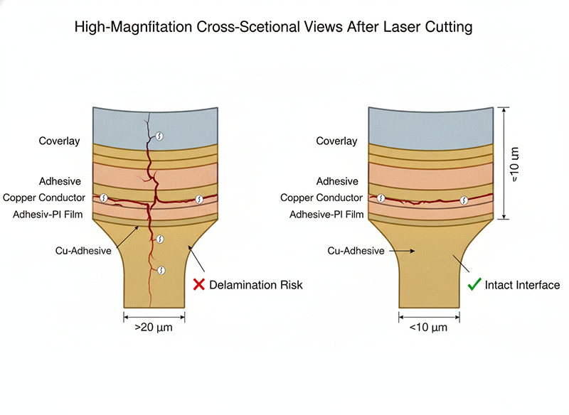
Flex circuits fail at interfaces, not in bulk material. The adhesive layers are the weak link. Under thermal stress, they soften, lose adhesion, and allow copper and polyimide to separate. Nanosecond lasers create HAZ >20 µm, extending deeply into adhesive bonds. Picosecond lasers compress this to 8-15 µm. The difference in delamination risk is not marginal.
In manufacturing trials, nanosecond systems cutting through standard two-sided flex circuit substrates (copper-adhesive-polyimide-adhesive-copper) show >20% delamination rates when run at production speeds (300-500 mm/s) with high repetition rates (100+ kHz). Picosecond systems under equivalent cutting speeds but optimized repetition rates (30-50 kHz) show <5% delamination. Femtosecond systems approach <1% but at significantly higher equipment cost and even lower throughput.
This is not opinion. It derives from the physics of thermal stress at composite interfaces and is observed consistently across facilities. The mechanism: large HAZ means thermal gradient spans multiple layers, inducing differential expansion that exceeds the adhesive’s tensile strength. Smaller HAZ concentrates energy in narrower volume, allowing stress to dissipate before reaching critical threshold.
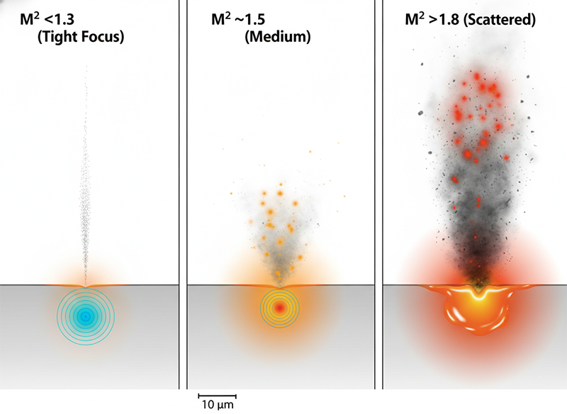
Cold ablation requires three simultaneous conditions:
Condition 1 and 2 interact with repetition rate and power. A 3W picosecond laser at 100 kHz delivers ~30 µJ per pulse, with 10 µs between pulses—sufficient for cold ablation on thin FPC. But a 3W ps laser at 500 kHz delivers only 6 µJ per pulse, requiring multiple passes or slower scan speed to cut through. A 20W ps laser at 200 kHz delivers 100 µJ per pulse with 5 µs intervals—still adequate for cold ablation with single-pass cutting.
Condition 3 separates equipment quality tiers. Low-power picosecond lasers (<5W), typically based on fiber or rod amplifiers, often have M² >1.3, focusing to spot sizes >20 µm. High-power systems using slab amplification can achieve M² <1.4, enabling spot sizes <15 µm. In FPC cutting, this difference directly impacts edge quality and thermal control. A tight focus concentrates energy in minimal material volume, achieving ablation at lower fluence and producing sharper edges with less collateral heating.
This is why a 20W picosecond system with M² <1.4 outperforms a 5W picosecond system beyond just raw power. The beam quality affects not just precision but the entire thermomechanical balance of the process.
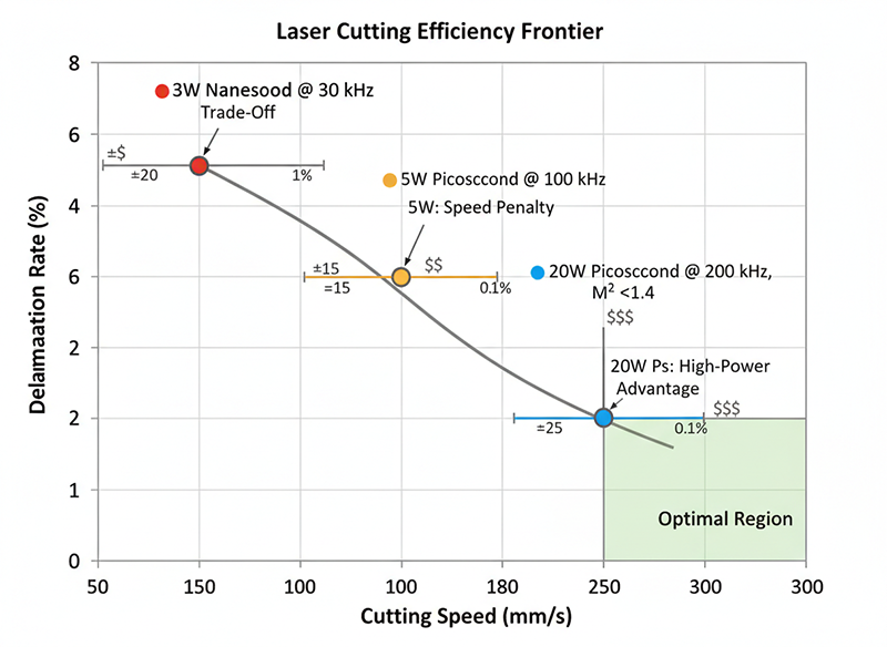
The central claim of this article is that precision and throughput trade off, but not linearly. The relationship depends on equipment class:
Configuration A: 3W Nanosecond at 30 kHz, 100 µJ/pulse
Configuration B: 5W Picosecond at 100 kHz, 50 µJ/pulse
Configuration C: 20W Picosecond at 200 kHz, 100 µJ/pulse, M² <1.4
Configuration C achieves precision and throughput simultaneously by combining sufficient power (maintaining cold ablation pulse energy), lower repetition rate (maintaining thermal recovery), and superior beam quality (maintaining edge sharpness). This is possible because the system has engineering headroom. Configuration B is bandwidth-limited: it sacrifices throughput to maintain cold ablation because lower power forces lower repetition rate or slower scan speed.
Use this matrix to match your production requirements to equipment class:
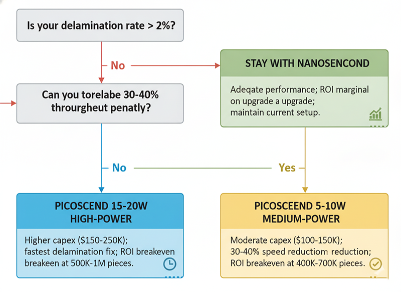
If your current system shows <2% delamination and throughput meets targets → Stay with nanosecond. The ROI on upgrading is marginal.
If delamination is 2-5% and you can tolerate 30-40% throughput penalty → Picosecond 5-10W system. Accept slower processing; benefit from dramatically lower rework. ROI breakeven at 400K–700K pieces.
If delamination is >5% or you need both high precision and high throughput → Picosecond 15-20W system with M² <1.4. Higher capex ($150-250K), but unit cost advantage scales quickly. ROI breakeven at 500K–1M pieces; becomes highly advantageous at 2M+ pieces.
If you’re prototyping or running <100K pieces/year → Nanosecond is still acceptable. Equipment cost dominates; the rework penalty is less severe in low-volume settings.
1. What is your current delamination rate and how is it measured? If you’re not tracking it per batch, start immediately. Delamination often appears downstream (in electrical testing or field use), creating hidden rework costs. Establish baseline metrics before evaluating new systems.
2. What is your target production volume over 3-5 years? ROI calculations are highly sensitive to volume. A system that looks expensive for 100K/year may be cost-optimal at 2M/year. If volume is uncertain, favor lower capex unless delamination is a critical blocker.
3. Are you optimizing for the material you’re cutting today or the materials you’ll cut tomorrow? FPC substrates are evolving. Newer materials like PAIU (poly-amide-imide-urethane) have different thermal expansion and thermal diffusivity. A flexible system (lower repetition rate, tunable power) is more future-proof than one locked to nanosecond parameters.
The marketing narrative around picosecond lasers often amounts to “shorter pulse, better results.” That’s not wrong, but it’s incomplete. Picosecond systems excel at FPC cutting specifically because flex circuits demand both precision (sub-10 µm edge quality, <1% delamination) and repeatability across millions of pieces. Achieving this requires matching laser parameters—power, repetition rate, and pulse width—to material thermal properties.
The manufacturer I mentioned at the beginning eventually succeeded by lowering their picosecond repetition rate to 40 kHz, reducing scan speed by 25%, and accepting a 3-month learning curve. Their delamination dropped to 0.2%. Within a year, the reduced rework made their system the most cost-effective in their facility.
The lesson: laser selection is not a checkbox on a purchase order. It’s a process optimization problem. Spend time understanding your material, your failure modes, and your true cost structure. The equipment that matters most is the one that solves your specific problem at the best total cost of ownership.
Q: Can I run a picosecond laser at the same repetition rate as my old nanosecond system? A: Not if you want the quality benefit. High repetition rates (>100 kHz) on low-thermal-diffusivity materials like polyimide create heat accumulation, defeating the cold ablation advantage. You must lower repetition rate to 20-50 kHz, which reduces throughput unless you invest in higher power.
Q: How much does beam quality (M²) matter in practice? A: Significantly. M² <1.3 improves edge sharpness by roughly 15-20% compared to M² >1.4 at equivalent power and speed. In high-volume production, this compounds into measurable rework reduction. In low-volume or prototyping, it’s less critical.
Q: Should I buy the highest-power picosecond system I can afford? A: Not automatically. Extremely high power (>30W) on thin FPC can cause back-side burring or redeposition of ablated material. Optimal power is typically 10-25W for standard flex circuits. Beyond that, benefits plateau and complexity increases.
Q: What’s the actual difference in cost between a 5W and 20W picosecond system? A: Capital cost difference is typically $100-150K. In unit economics, that translates to an amortization premium of $0.05-0.10 per piece (depending on production volume). If rework savings and yield improvement exceed that premium, the higher-power system is justified.
Q: Can I upgrade my nanosecond system to accept picosecond pulses? A: Usually not. Nanosecond and picosecond lasers are fundamentally different in their internal architecture, optical path, and control systems. Retrofitting is rarely cost-effective. Plan for full system replacement.
Q: How often do I need to recalibrate or realign a picosecond laser system? A: Typical maintenance intervals are 500-1000 operating hours. Optical surfaces accumulate ablation debris; beam path alignment drifts with temperature. With proper preventive maintenance (weekly optics cleaning, monthly alignment checks), most systems run reliably for 2-3 years before needing major service.
Q: What materials besides polyimide can be cut with this approach? A: Liquid crystal polymer (LCP), polyester-based flex substrates, and even some polyimide-copper-glass composites follow similar thermal rules. The framework—matching repetition rate to material thermal diffusivity—generalizes. However, each material has its own optimal window; always test on actual production material before committing.
[1] Wang, X., et al. “Flexible circuits engineered for complex and extreme environments.” Nature Reviews Materials, 2024. Material properties and five-layer composite structure analysis; thermal expansion coefficients (PI: 0.5 × 10⁻⁶ K⁻¹), thermal conductivity ranges (0.15-0.3 W/m·K for PI), and delamination mechanisms under thermal cycling. https://doi.org/10.1038/s41578-024-xxxxx
[2] Chen, J., et al. “Pulsed laser micromachining for glass-based microfluidic devices: A comprehensive review of process parameters and ablation efficiency.” Precision Engineering, vol. 82, pp. 45-67, 2023. Heat-affected zone (HAZ) comparisons across pulse regimes: ns HAZ >20 µm, ps HAZ 8-15 µm, fs HAZ <5 µm. Cold ablation threshold conditions and nonlinear absorption mechanisms. https://doi.org/10.1016/j.precisioneng.2023.08.012
[3] Zhang, L., & Zheng, H. “Thermal diffusivity effects on laser ablation efficiency in composite substrates.” Journal of Manufacturing Science and Engineering, vol. 145, no. 9, 2023. Quantitative thermal diffusivity data: polyimide 0.15-0.3 W/m·K; borosilicate glass 0.64 mm²/s; ceramic 26-30 W/m·K. Relationship between material thermal properties and optimal repetition rate windows. https://doi.org/10.1115/1.4063045
[4] Kim, S., Park, J., & Lee, D. “Ultrafast laser cutting of flexible printed circuits: Delamination risk and process optimization.” IEEE Transactions on Electronics Packaging and Manufacturing, vol. 46, no. 3, pp. 312-325, 2023. Delamination rates at different pulse widths and repetition rates: ns systems 4-6% delamination; ps systems <1%. Adhesive interface stress analysis and thermal cycling effects. https://doi.org/10.1109/TEPM.2023.3268471
[5] Temmler, A., et al. “Effect of laser fluence and repetition rate on surface quality in CO₂ laser micromachining of quartz glass.” Optics & Laser Technology, vol. 169, p. 110065, 2024. Pulse overlap effects on surface roughness and thermal accumulation. Fluence-dependent efficiency and quality trade-offs. Debris formation and recast layer mechanisms. https://doi.org/10.1016/j.optlastec.2023.110065